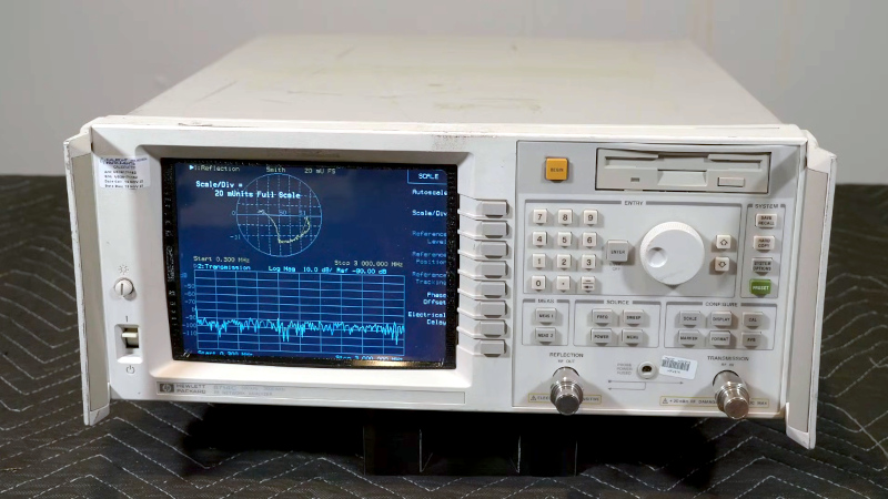
A Vector Network Analyser, or VNA, is the ultimate multi-tool of RF test equipment. They can now be had in not very capable form for almost pocket money prices, but the professional-grade ones cost eye-watering sums. Enough to make an older VNA for a few hundred on eBay a steal, and [W3AXL] has just such a device in an HP 8714C. It’s the height of 1990s tech with a floppy drive and a green-screen CRT, but he’s homing right in on the VGA monitor port on the back. Time for a colour LCD upgrade!
There are two videos below the break, posted a year apart, because as we’re sure many of you will know, events have a habit of getting in the way of projects. In the first, we see the removal of the CRT module and safe extraction of its electronics, followed by the crafting of a display bezel for the LCD. Meanwhile, the second video deals with the VNA itself, extracting the VGA signal and routing it forward to the new module.
We’re struck not for the first time by the high quality of the construction in this piece of test equipment; it’s not only substantial but well designed for maintenance and disassembly. [W3AXL] sensibly leaves the RF part alone, but both CRT and mainboard modules slide out with minimal screw removals and few problems in reassembly.
He goes the extra mile with a second iteration of the display mount and a curved print to fit the CRT shape in the front panel. The result is a colour display on the instrument, and we’re guessing, a much lighter device, too.
If VNAs are new to you, then you might wish to learn a little about them,


Just did this with one of the old VNA’s at work (a wonderful little old HP8753A).
CRT I took out makes a wonderful paperweight!
Well done. Normally, I don’t like LCDs to substitute CRTs,
but from about 400 lines onwards an LCD monitor is usable.
The standard VGA resolution of 640×480 for example has enough density that an LCD/TFT won’t reveal so much pixelation anymore.
With 320×200 and similar low resolution modes a CRT screen really helps to smooth out things.
So if that thing was using a C64 as a controller, the CRT would still have been the better solution. ;)
In an NVA, spectrum analyzer or oscilloscope, a flat screen might have lower noise level, also, which is positive.
Provided that it won’t generate RF noise by its circuit board or the background lights (CCFL PSUs, LEDs using PWM dimming mode etc).
Anyway, these are just my two cents here. 😅
I was sold at – the markers are in a different color so you can actually tell them apart from the rest…
” be had in not very capable form ”
?????
The NanoVNA has been compared to a HP VNA and did well.
They are VERY capable for the cost.
I’m curious: my (layman’s) understanding is that there was a time when oscilliscopes with CRTs had a ‘direct’ connection between signal and display; like a much better designed and engineered version of the old trick where you just pull the yoke on a CRT TV and drive it with output from an audio amp to watch that deflect the electron beam, then go for 2d patterns by letting left channel handle one of the coils and right control the other one. Then get a little cleverer and run audio through one coil and a repeated wave through the other so it sweeps back and forth regularly to stretch the audio waveform out a bit. Obviously that’s a janky hack; but just the analogy: the workings of the display actually represented the input with some analog transformations along the way, with analog signal path limitations but not specific quantization or digitization.
Then, at some point, relatively fast and capable ADCs became available; and, while CRTs were still the likely output for cost reasons, the ‘real’ output gradually came to be basically the framebuffer that the system was trying to render for you(or would sometimes offer to save to floppy or to connected PC) rather than being an analog deflection of the CRT’s electron beam(limited by analog bandwidth and phosphor deposition evenness; but not fundamentally pixelated).
When was that cutover, roughly; and was it more or less a full switch immediately; or were there intermediate units that were mostly of the traditional type but gradually grew limited abilities to snag digitized outputs of analog values at particular times and it was a shift in multiple steps?
Hi, I’m just a layman, too, but I can think of several types.
a) analog oscilloscope
b) analog storage oscilloscope (using storage tube CRTs etc)
c) hybrid scope, half analog/digital (analog waveform directly drawn to CRT, but digital overlay with text/data)
d) digital oscilloscopes (ADC)
Those types before the digital oscilloscope were still in wide use up until the late 20th century (1990s).
In my country, the older term “oscillograph” was still in use back then.
Because the electron beam drew on a screen, similar to the old oscillographs which drew on paper using needles.
why though? if it works…
as a kid I used to “mod” my stuff all the time and nowadays I just try to keep it original whenever possible.
some things , obviously, I don’t care about, such as old mechanical hard drives that can be easily replaced by solid state
I have an 8713B (unlocked to be a 8714B just like this one) and the CRT in it is beautiful and bright. and not burned in.
as for the hackaday note on weight reduction: lol oh god no. the 871xB series is ridiculously heavy but the heaviest part is the case itself. it’s made of thick sheet metal.
Funny how “retro-look” gets into upgrading. The original tube has square corners but the new “bezel” frame mimics the older curved glass tubes of TV’s mid-late twentieth century. Curved only because of vacuum inside, not some sort of style. The conversion seems to improve on readability though.