Poorly designed PCBs and enclosures that slowly cook the electrolytic capacitors within are a common failure scenario in general, but they seem especially prevalent in so-called Internet-of-Things devices. The SwitchBot Plug Mini that [Denki Otaku] took a look at after many reports of them failing is one such example.
These Mini Plugs are ‘smart’ plugs that fit into a regular outlet and then allow you to control them remotely, albeit not integrated into a wall or such like the Shelly 2.5 smart relay that also began dying in droves. Yet whereas with the Shelly relays this always seemed to take a few years to show up, generally in the form of WiFi connectivity issues, these SwitchBot plugs sometimes failed within weeks or start constantly switching the relay on and off.
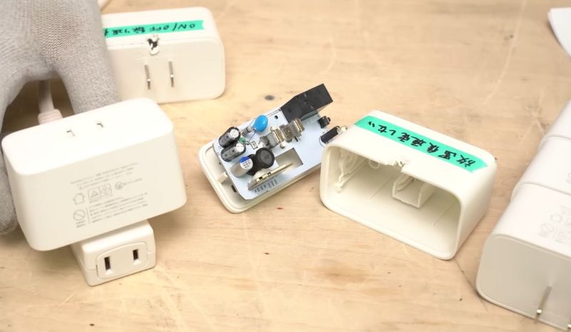
After SwitchBot started an exchange program for these plugs, [Denki Otaku] decided to examine these failed devices from affected users. Inside a dead unit the secondary side’s 680 µF capacitor was clearly bulging and had cooked off its electrolyte as a teardown of a dead capacitor confirmed. After replacing this one capacitor a formerly unresponsive plug sprung back to life.
This failed capacitor is important as it serves as the buffer for the 3.3 V rail, which otherwise sags below the operational range of the microcontroller during power-hungry WiFi operations, causing it to reset. As for the question of why this failure happened, there are two possibilities: one involves the B- or C-tier capacitor – for which no datasheet could be found – being unsuitable for dealing with the ripple current it was exposed to, the other being the high temperatures in that section of the PCB.
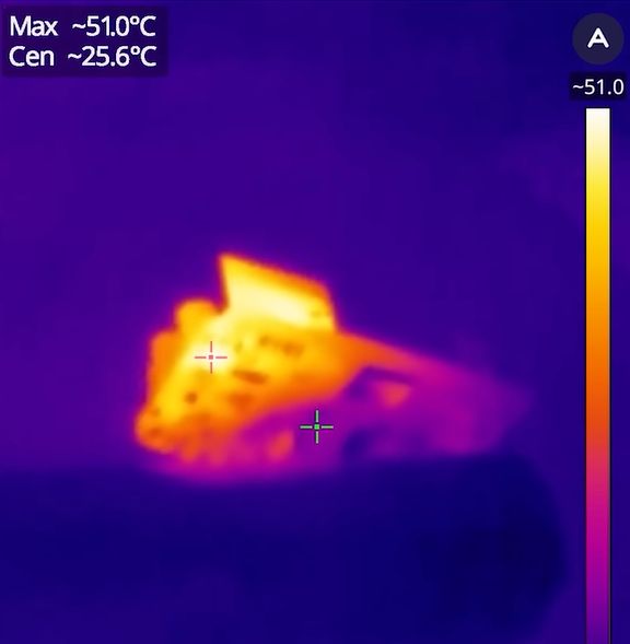
As a thermal image of the working PCB shows, the voltage regulator and switching circuitry present on the PCB – right below where the failed capacitor is located – reach a temperature of up to about 50°C, without taking into account the sealed enclosure that the PCB is located in.
The WiFi module that is located next to the capacitor and sticking up vertically from the PCB also reached a similar high temperature, making sure to bake the affected capacitor from below and the side. Even in open air the capacitor reached a temperature of about 43°C.
While a higher-quality capacitor will very likely cope with ripple current better, ultimately it’s pretty much just an unnecessarily stressful environment for electrolytic capacitors. While investigating two newer batches of these Plug Minis that are not subject to recall, the older unit still had the same flawed capacitor, while the new unit had replaced it with what looks like a polymer capacitor with the same ratings.
Interestingly, one of the failed plugs that [Denki Otaku] got sent did use one of these polymer capacitors, but appears to have another fault that wasn’t further investigated. Either way, the use of a polymer capacitor seems to help with the longevity to get it at least past the warranty period, but without a redesign these units seem doomed to fail due to rapid capacitor aging.


i already have problems filling the 72 frames on my half frame cameras or the 52 on my 24×24 one.
I have SO many of these that have failed.
They are great in that they are cheap esp controlled switches that are easy to reflash…but dang do the relays fail.
edit – where is the exchange program for them i cant find it
A good improvement would be to remove the relay and replace it by a triac and optocoupler , I might do this to one of the smart plugs that I have
Why would you accept lower efficiency just for the off chance that you have to use dimming once function once in a while?
Realistically its really quite difficult to wear out a relay by just operating it normally, so even the solid state switching having a longer lifespan isn’t a valid reason
A lightly loaded triac would create less heat than a relay coil. It will also draw less current from the smps and lower ripple current in the output cap.
This is great investigative work on a failing unit and the heat killing the cap.
680uF is a fairly large cap for a modern iot wifi radio, especially the ESP32 which has 22uF in some of its reference designs.
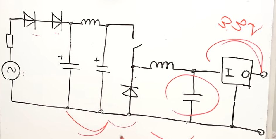
This looks like the DC:DC buck convertor has a low switching frequency and cannot respond quickly to the current spikes of the Wifi radio and integral power amp. The cap feels like a bandaid to ride out these current spikes rather than responding to them by pulling more current from the mains AC.
A higher frequency switcher would have let them use a lower capacitance here and avoided an electrolytic completely and improved product lifespan. I’d suspect this switcher and the elctrolytic were cheaper and worked adequately on the bench.
I didn’t realize you could still sell a product with only half-wave rectification due to their poor power factor on the mains power.
The cap needs to keep the supply rail steady when the relay switches. It needs to supply current to operate the coil and absorb energy when the coil is switched off.
Don’t have the switchbot plug, but I do have the candle warmer, and the control puck gets very hot to the point of too hot to touch. They did replace it and it still gets very hot but tolerable to touch. I am seriously considering opening up the faulty(?) one and seeing what component is causing the searing heat.
This reminds me of when I used Insteon years ago…I switched away from X10 because it was unreliable (interference from a cheap wall wart, random triggering). I used Insteon for a few days, and it was exactly as unreliable…and on top of that, every unit got hot whether it was on or off. That really surprised me…i really don’t believe you have to get hot to monitor for a small RF signal on my house wiring. I’m less confident that it’s possible to do minimal wifi without getting hot, though somehow my phone does it!
I would still file this product under garbage if it gets hot just sitting there. Even if it did have caps that could survive it.
Just not a worthwhile overhead. Really doesn’t pass my smell test.