
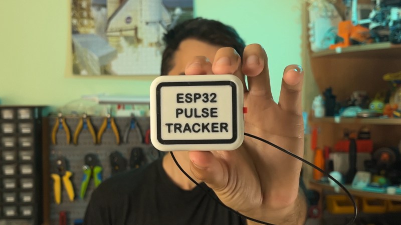
If you spend any time near a gym, you may be familiar with Bluetooth heart rate monitors — a small pack of electronics mounted on a strap round the chest which can relay heart rate data to an external logger or display. We’re pleased to see [Milos Rasic]’s project then, an open-source version of one of those monitors.
The heart rate capture is done by an AD8232, while the Bluetooth part is handled by a Seeed Studio XAIO ESP32 board. Power is provided by a single 3.7 V cell, with a boost converter to push that up to 5 V. The design omits a charge controller to keep things simple, so figuring out how to top off the cell is left as an exercise — no pun intended — for the user. Software is loaded through the Arduino IDE, which raises the possibility that other ESP32 CPUs could be supported with a bit of modification. All in all it’s a surprisingly simple project, and while the manufactured version is cheap enough it’s still very much worth having one that’s open source.
If you’d like to know more about his quest to develop open medical devices, check out the talk [Milos] gave on the intricacies of blood pressure monitoring earlier this year at Hackaday Europe.











I have seen a guy shortly after he had had open heart surgery, so no matter what rate it monitors, I think I’d rather keep my chest closed, thank you 😜
I wonder if it need 10 or 100x times more power compared with a Polaris H10. :-D
I’m also surprised people choose ESP32 for battery powered projects.
The nRF52 MCUs uses a lot less energy, has built in buck converter and they have an example of a simulated HRM in their SDK. There are plenty of modules to buy for them too. An nRF54L will draw even less, but I don’t remember if it can run directly from the battery.
Thank you for this information. I haven’t worked with HRMs so finding a link like this is very useful. Again, thank you.
100x, especially if you start at 3v7, boost it to 5v, then ldo it back to 3v3.
Indeed fascinating, to see the voltage being boosted from 3.7 -> 5 at an efficiency of about 90% (let’s be optimistic here). Then dropped down back to 3.3, causing another efficiency step of 66%, so the total efficiency going from 3.7 -> comes down to 60%.
If the battery was to be connected directly to the 5V input (which should be ok as the board doesn’t need 5V) the efficiency would be 90%, the LDO on the ESP board wouldn’t have to work that hard, the battery would function longer, the system could be smaller/lighter/less complex.
It’s all fun those little boxes of dev boards you can cobble together into on big project, but it loses the concept of what you are actually making this way. The fun thing is that you actually can get away with it (it works, doesn’t it). And that’s exactly the same problem with software development, we can create the most wonderful programs, by adding libraries and modules to projects, not knowing what happens underneath… but it works. Sure, suddenly we need a 3GMHz CPU with 32Gig of RAM and 2TB SSD (minimum specs) to run it all smoothly, but hey… it works doesn’t it.
And now we have AI… a machine that imagines even sillier contraptions, of which nobody knows exactly how it works, but it works… it needs even more resources… etc.
With this mindset… true progress is doomed.
Buck is more efficiency than boost. As you say on a good day you might get 90% out of the boost side (3.7v –> 5v) while buck (5v –> 3.3v) can be as high as 95%.
At best that might be only a ~15% loss, more likely over 30%.
Sure it makes the power supply simple, but yeah…
“The current plan for this project is to design a PCB around a new AFE IC”
Use the AD8232, it’s well suited for your project, but since you are using a strap anyway, connect it in a two electrode config (that means, use the RLD pin of the chip to directly drive the inputs of the instrumentation amp via 10 MOhms, see AD8232 datasheet).
And yes, use another controller which needs a lot less power. Reference – a Polar H10 can live from a new CR2032 coin cell for approximately 400 active hours ;)
Nevertheless, nice proof of concept that you can design an HRM using available building blocks.
fyi, pic12 is designed to run on an unconditioned battery supply, 2V to 5.5V, but the AD8232 only supports 2.0V to 3.5V. shrug
i’m less interested in the question of how can we connect the ad8232 to a mcu (seems like an uninteresting solved problem) and more interested in how to actually measure heartrate. i have tried a couple HRMs, and haven’t found them to be usable. i got one from temu and it would say my heart rate decreased when i was exerting, which i took to mean that it was a fake product. but then i got a fitbit and it said the same thing. surprisingly, it was very reliable about this, and it showed that even if my arm was fairly still (i.e., biking instead of running). i strongly suspect that when my heart rate spikes, some common heuristic winds up halving the rate, some sort of aliasing or aliasing-compensation. i’m not sure if an ECG-based monitor might do better but i’m not optimistic due to the difficulties of maintaining electrical contact through both motion and time / sweat.
i imagine that many people using bio-monitors are getting absolute garbage results and have no idea. they haven’t followed the basic scientist’s discipline of measuring the same quantity 2+ ways to sanity-check a new data source.
the irony is, when i am exercising, i can feel my pulse pushing against the watch band. surely this isn’t actually a hard problem to solve properly. investigating it would be a great activity for a hacker!
ECG-based monitoring is used by all professional athletes and serious amateurs in endurance sports. The products from known brands work very well when moving and sweating.
The optical monitors work well for some, not so well for others. You have big brands like Garmin, Apple and Samsung that can’t solve it for all, it surely isn’t an easy problem to solve.