
If you wanted to extract the firmware from a mystery device, you might pull the flash chip out of it and toss it into a reader. But if you only had one chance to get it right and couldn’t risk damaging the device in the process, physically removing the chip may seem much less attractive. Reading the chip in-circuit failed — because of course it did — so what does that leave?
Well, if you follow the example of [Matthew “wrongbaud” Alt], the next tool you reach for might be a logic analyzer. In a recent write-up, [wrongbaud] explains the process of identifying, capturing, and ultimately decoding the SPI read operations used to load the firmware from a common W25Q-series flash chip at boot time. He notes it’s not a perfect solution, as in the end you’ll only be able to sniff out what the CPU actually reads, not necessarily the entire contents of the chip, but it’s a big step in the right direction if you’re reverse engineering something in the dark.
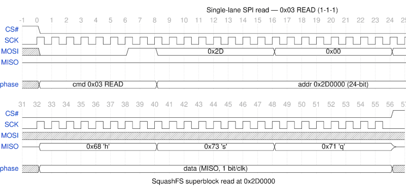
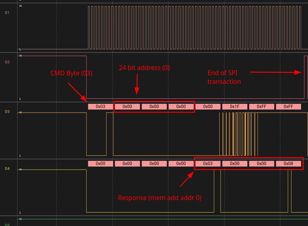 Before digging into the decoding of the captured data, [wrongbaud] does what he does best and breaks down the nuts and bolts of SPI communication. Armed with the output from his logic analyzer and the datasheet for the flash chip, he explains how to interpret the various signals at play.
Even if you’re not terribly interested in slurping the firmware from mystery boxes, it’s a great primer on how SPI works and a fascinating read for anyone who’s looking for a better understanding of how chips talk to each other.
Once he’s covered the basics and captured some data moving across the SPI bus, [wrongbaud] moves on to decoding it with Scapy. The powerful Python tool is most commonly associated with the manipulation of network packets, but as demonstrated here, it can be turned loose against other types of data. With a little massaging, it can work through the capture files produced by the logic analyzer and turn it into an image file ready to get loaded into binwalk.
But wait! Just when you think [wrongbaud] was done, he notes something a little odd — the firmware image contains the bootloader and Linux kernel, but there’s a big gap where the filesystem should be. It turns out there’s a little more work to be done, as before the CPU loads the filesystem off of the chip, it kicks into the faster Quad-SPI, which adds two more data lines to the mix. That means more capturing, a dash of extra processing, and a dd one-liner to merge the two image files into one, but [wrongbaud] gets us there in the end.
If this is the first time you’ve run across [wrongbaud]’s work, you’re in for a treat. From his overarching hardware hacking roadmap to deep dives into individual techniques such as fault injection, he’s produced phenomenal content that’s almost guaranteed to teach you something new.












Matt/Wrongbaud content is as always top notch! Thanks for the read! I hope one day to be able to afford his courses
Shoot me an email, I can send you a hardware list and some write ups to get started :)
Hey Nath!
Wrongbaud here – ping me via email or twitter and I’ll send you a list of gear to get for the course and share some of the modules with you!
I build out a pcb that connects the logic analyzer directly to a pico. So that i can replay/simulate any device via ai
what
Vibecoded comments
I did not know the bar today is so low.
Some years back I did a similar thing on a SPI flash – a BIOS chip on one of the HP Moonshot modules. The quest here was to see what it does. I have captured some nice reads using a Cypress FX3 based software defined logic analyzer (it samples the data and runs some triggers and protocol decode in real time or from a replay).
What I saw in reads was the intel partitioning of the firmware flash, software straps, then classic x86 bios startup, switch to protected or rather to say an unreal mode – and when the first port 80 access came – that is directed through the LPC bus, the system went silent. A total proof that this one suffered that famous Avoton C2000 AVR-54 bug.
The SPI transactions were not per instruction though, but fetched per cache-line, the few opcodes that were actually executed I decoded by hand.. it was a pre-AI era project. I did an analysis I needed, felt no need to share it, as it was obvious like – eating when you are hungry.
Make a full writeup, and send it into the tipline.
Luxury! In the dim and distant past of the 1990s, I had to snoop and decode 32 data / 16 address bus. A monster HP analyser collected the data, but muggins had to decode it. Such fun…
I started off in the late 70s.
To paraphrase the Four Yorkshiremen: We made us own tools back then :)
Nice – for this target, the transactions were also not per-instruction. They were on boot when it was reading in the initialization code, but afterwards when it switched to QSPI the transactions were much longer and used the fast burst read command.
I mostly wanted to publish this because as far as I could tell there was no open source examples of how to do this. It’s certainly not ground-breaking but hopefully it helps some folks in future! The main goal was to explain to readers how SPI transactions work, and hopefully teach them a thing or two about reverse engineering in the process!
This is the other Daniel, here. Thank you for posting your write up. I found it quite interesting and well written.
a glasgow plugin for automating this would be nice. ought to be able to handle decent clock speeds, too, while just sending across decoded reads/writes