
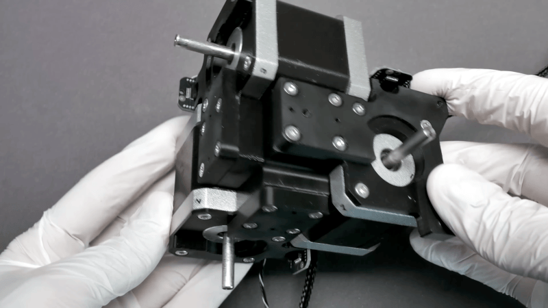
If you need a micro-manipulator, you probably already have a good idea of what it does. For example, you might be moving a probe over an IC die or wafer. You might be looking at something through a microscope. The key is moving something in very small, precise increments along three axes. An open-source design for a micro-manipulator has seen significant improvements lately. You can see several videos about the device below.
The device uses stepper motors, parallel kinematics, and miniature ball joints to achieve precise motion. The recent version 4.0 update fixes a few problems. According to the GitHub page:
- Self-collision during homing fixed.
- Connection of the ball joint block with screws only was not well constrained and could be rotated a bit.
- No reliable way to ensure consistent linkage rod length
- Unnecessary ball joint friction
- Accurate ball position heavily dependent on print quality and corner rounding
- Rubber bands could not be changed or removed once glued in.
We’ve covered earlier versions of this device, and we were watching the improvements to the ball joints. Since then, the project has updated much of its mechanical design and documentation, and it has also changed the API that drives it. It can even use tools in g-code now to support things like fine control over laser engraving.
If you prefer something old-school manual, consider a 3D-printed one.









Love it! When I can I get this in a 3D printer or CNC tool? Without costing an arm and a leg, of course
I imagine the print head or especially CNC mill would have to be similarly optimized for micro-work. Run-out and vibration on a dremel tool is going to be pretty significant. I wonder what would be required for tool head modifications
Two very obvious applications are probably the use of lasers and microfluidics. One field of study is electrostatics; with these steps, the electrostatic force is very powerfull.
And electromagnetic glitching of chips for hardware hacking