
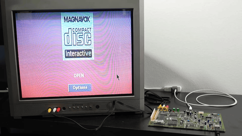
The Philips CD-i is a console with many shortcomings, and those include the power supply. For whatever reason, the engineering team decided it should use an 8P8C connector just like Ethernet. Thus, just like your Ethernet cables, it has that annoying problem of the tab snapping off all the time. [MattKC] wondered if the CD-i could benefit from a USB power upgrade instead, and set about making it a reality.
The plan was simple enough—get the CD-i running off of USB-C instead of the ungainly original power supply that shipped with the unit. Given the console runs almost exclusively off of 5 V power, it should have been pretty easy. Only, the original spec adds one little detail that makes things a bit harder. The console is designed to draw up to 3 A from the 5 V line, while also having a -5 V line at 0.2 A. If not for that negative supply, it would have been easy to run the unit off any old 15 W USB-C charger spitting out 5 V. That extra negative line complicates things, because while the negative line could be created with some supporting electronics, it’s hard to find that extra watt from most chargers. While there are plenty of higher-wattage USB-C chargers, the majority tend to use higher voltages to deliver the additional power, capping the 5 V output at 3 amps.
Thus, it was necessary to work a little harder. [MattKC] decided to build a board that would negotiate with a USB-C charger for 9 V operation to get the power budget necessary. This would then be stepped down to 5 V, while there would also be an inversion step to supply the -5 V line, too. A CH221K chip does the job of negotiating a 9 V USB-C power supply, while a TPSM84538 steps the voltage down to 5 V with the capacity to supply up to 5 A. An LT3580 chip then inverts this voltage for the 5 V line. There’s also a power switching circuit on board because the CD-i included some of that functionality in the original power brick.
If you’ve got a CD-i and you’re sick of fussing with the original power supply, this could be a great upgrade. We’ve also explored USB Power Delivery in detail before, if you need a primer.









There’s a USB-C power mod for the Amiga, though it’s rather more expensive than a new power supply.
Doing it the way shown in the video is much better for long term use but there is a way to combine USB chargers to do the same thing.
Mains powered USB chargers are usually isolated. Just to be clear they usually have isolation between the mains supply and output side, there is usually not isolation between multiple USB outputs on the same charger, they usually share a common ground.
So if you have two separate mains powered USB chargers that have isolated/floating outputs then they can be combined in series to either get a positive and negative rail or to get an increased voltage. It works with PD too, so with two chargers that can supply 20 V, you can get positive and negative 20 V rails and use the midpoint as ground or you can get 40 V.
However before you try make sure that the USB output is isolated and never use two ports on the same charger unless you know for sure it’s outputs are isolated from each other which is generally not the case and I have never seen it.
It can be better than using cheap negative voltage generators or split supplies that usually have a very weak negative rail that is sometimes quite unstable too and instead you get the rating on the charger, so 5 V 3 A and -5 V 3 A for example.
Yeah, MattKC is pretty awesome! Too bad other people try to take credit for his work.