Objective Hotend Performance Measurement Is Hard

Evaluating the performance of 3D printers and component upgrades is a more difficult than it may seem at first glance, and subjective observations can lead to incorrect conclusions. To objectively determine the maximum flow rates of different FDM 3D printer hotends, [MirageC] is developing a robust testing standard backed by more than just visual observations.

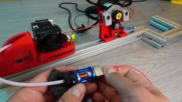
Defining the max flow rate threshold is not straightforward. A common method is to run a test print while slightly increasing the flow rate with each layer, and visually making a judgment on the last acceptable layer. It would be easy to miss errors, or unconsciously be inconsistent with observations over time. [MirageC] wanted to back up observations with measurements. To do this, he is measuring the true feed rate of the filament with an encoder wheel, and the backpressure of the filament on the extruder using a load cell. A Bowden tube helps to isolate the extruder from the vibration of the moving printhead.

After much testing, [MirageC] determined that the numerical threshold would be a specific deviation percentage between the desired and actual flow rate. At temperatures above 230°C, [MirageC] found that the last visually acceptable layer was consistently around 5.75% flow rate deviation for one specific PLA filament. It does not mean that 5.75% will be the magic number for all filaments and nozzle size, but it does provide a measurable parameter to back up visual observations.

In a world of questionable product reviews this dedication to objectivity is a breath of fresh air. If you are looking to upgrade your 3D printer’s hotend [MirageC]’s tests would be a good source of information.

Continue reading “Objective Hotend Performance Measurement Is Hard”

Flapping PCB Fan Blows A Little Bit

Moving air with spinning blades is the most popular way, but it is not the only way. Using the PCB actuator technology he has been working on for the past few years, [Carl Bugeja] built a small electromagnetic flapping fan using a custom flexible PCB.

Inspired by expensive piezoelectric fans ($400 for a 30mW fan), [Carl] wanted to see if a cheaper alternative could be made. Using a similar design to his other PCB actuators, he had a custom flexible PCB made with an integrated coil, which can flex on two thin supports. These supports also contain the power traces for the coil. By sticking the base of the PCB between two neodymium magnets, it can flap back and forth when driven by an alternating current. It produces a bit of airflow, but nearly enough to be useful. The power traces in the thin supports also break after an extended period of 180° flapping.

Although this probably won’t be a viable replacement for a rotary fan, it would be interesting to see how far one can push this approach by optimizing the design and magnet arrangement.

Continue reading “Flapping PCB Fan Blows A Little Bit”

High-Speed RC Car Needs A Flight Controller

The fastest ground vehicles on earth are not driven by their wheels but by an aircraft jet engine. At world record speeds, they run on an aerodynamic razor’s edge between downforce, which limits speed, and liftoff, which can result in death and destruction. [rctestflight] wanted to see what it takes to run an RC car at very high speeds, so he built a ducted-fan powered car with aerodynamic control surfaces and an aircraft flight controller.

This high-speed car is built on the chassis of a 1/14th scale RC buggy, powered by 4 EDF (electric ducted fans) mounted on a very long aerodynamic foam board shell. It also has an aircraft-style tail with elevons and rudders for stabilization and control at high speed using an ArduPilot flight controller. The flight controller is set up to stabilize in the roll and yaw axis, with only fixed trim in the pitch axis.

[rctestflight] got the car up to 71 MPH (114 km/h), which is fast for most RC cars but well short of the 202 MPH RC car speed record. It was still quite hard to keep in a straight line, and the bumpy roads certainly didn’t help. He hopes to revisit the challenge in the future with larger motors and high voltage batteries.

Continue reading “High-Speed RC Car Needs A Flight Controller”

Knife Throwing Machine Gets The Spin Just Right

Despite how it might appear in bad action movies, throwing a knife and making it stick in a target is no easy feat. Taking inspiration from the aforementioned movies, [Quint] and his son built a magazine-fed knife throwing machine, capable of sticking a knife at any distance within its range.

Throwing a sharp piece of metal with a machine isn’t that hard, but timing the spin to hit the target point-first is a real challenge. To achieve this, [Quint] used a pair of high-performance servo motors to drive a pair of parallel timing belts. Mounting a carriage with a rotating knife-holder between the belts allows for a spinning throw by running one belt slightly faster. The carriage slides on a pair of copper rails, which also provide power to the knife holder via a couple of repurposed carbon motor brushes.

At first, the knife holder was an electromagnet, but it couldn’t reliably hold or release the stainless steel throwing knives. This was changed to a solenoid-driven mechanism that locks into slots machined into the knives. Knives are fed automatically from a spring-loaded magazine at the back as long as the trigger is held down, technically making it full-auto. To match the spin rate to the throwing distance, a LIDAR sensor is used to measure the distance, which also adjusts the angle of the aiming laser to compensate for the knife’s trajectory.

The development process was fraught with frustration, failure, and danger. Unreliable knife holders, exploding carriages, and faulty electronics that seemingly fired of their own accord were all challenges that needed to be overcome. However, the result is a machine that can both throw knives and nurture a kid’s passion for building and programming.

Continue reading “Knife Throwing Machine Gets The Spin Just Right”

Optimising An RC Tilt-Rotor VTOL

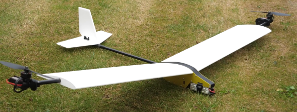
There are a variety of possible motor configurations to choose from when building a fixed-wing VTOL drone, but few take the twin-motor tilt-rotor approach used by the V-22 Osprey. However, it remains a popular DIY drone for fans of the military aircraft, like [Tom Stanton]. He recently built his 5th tilt-rotor VTOL and gave an excellent look at the development process. Video after the break.

The key components of any small-scale tilt-rotor are the tilt mechanism and the flight controller. [Tom]’s tilt mechanism uses a high-speed, high-torque servo that rotates the motor mount via 3D printed gear mechanism. This means the servo doesn’t need to bear the full load of the motor, and the gearing can be optimized for torque and speed. [Tom] also used the tilting motors for yaw and roll control during forward flight, which allows him to eliminate all the other conventional control surfaces except for the elevator.
Continue reading “Optimising An RC Tilt-Rotor VTOL”

Large Tip Driven Copter Turns Very Slowly

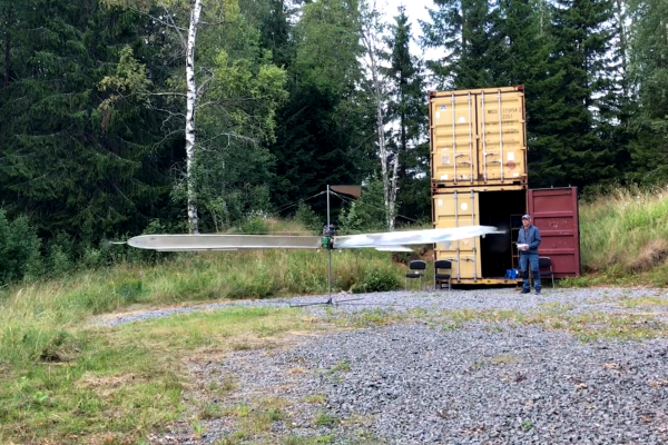
Picking propeller size for any aircraft, but especially VTOLs, it’s a tradeoff between size and RPM. You can either move a large volume of air slowly or a small volume of air quickly. Small and fast tend to be the most practical for many applications, but if you’re thinking outside the box like [amazingdiyprojects], you can build a massive propeller and make it fly at just one revolution per second. (Video, embedded below the break.)

One of the challenges of large propellers is their high torque requirements. To get around this, [amazingdiyprojects] drives the 5m diameter propeller from the tips using electric motors with propellers. The blades are simple welded aluminum frames covered with heat-shrunk packing tape, braced with wires for stiffness.

The flight controller, with its own battery, is prevented from spinning with the blades by counteracting the spin of a small DC motor. Each blade is equipped with a servo-driven control surface, which can give roll and pitch control by adjusting deflection based on the blade’s radial position.

[amazingdiyprojects] control setup is very creative but somewhat imprecise. Instead of trying to write a custom control scheme, he configured the old KK2.15HC flight controller for a hexacopter. Each control servo’s PWM signal routes through a commutator disc with six sectors, one for each motor of the virtual hexacopter. This means each of the servos switches between six different PWM channels throughout its rotation. To compensate for lag when switching between channels, [amazingdiyprojects] had to tune the offset of the commutator disc otherwise it would veer off in the wrong direction. After a second test flight session to tune the flight controller settings, control authority improved, although it is still very docile in terms of response.

Continue reading “Large Tip Driven Copter Turns Very Slowly”

Solar Plane Might Be Able To Last Through The Night

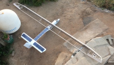
“Just add solar panels to the wings” is a popular suggestion for improving the flight times of fixed-wing drones. However, the reality is not so simple, and it’s easy to hurt rather than help flight times with the added weight and complexity. The team at [Bearospace Industries] has been working on the challenge for the while, and their Solar Dragon aircraft recently had a very successful test flight, producing about 50% more power than it was consuming.

Instead of just trying to slap solar panels to an existing plane, an airframe should ideally be designed from the ground up as a balancing act between a range of factors. These include weight, efficiency, flight envelope, structural integrity, and maximum surface area for solar panels. All the considerations are discussed by [Bearospace] in an excellent in-depth video, which is an indispensable resource for anyone planning to build a solar plane.

[Bearospace] put all the theory into practice on Solar Dragon, which incorporates over 250 W of high-efficiency Maxeon C60 solar cells on the wing, tail, and triangular fuselage. The cells were wired to match their maximum power point voltage as closely as possible to the plane’s 3S lithium-ion battery pack, enabling the solar cells to charge the battery directly. To prevent overcharging, a solid state relay was used to disconnect the solar cells from the battery as required.

The batteries maintained the same average state of charge during the entire one-hour late morning flight, even though the panels were only connected 65% of the time. The team expects they might be able to get even better performance from the cells with a good MPPT charger, which will be required for less than ideal solar conditions.

Solar Dragon has a much larger payload capacity than was used during the test flight, more than enough for an MPPT charger and a significantly larger battery. With this and a long list of other planned improvements, it might be possible for the Solar Dragon to charge up during the day and fly throughout the night on battery power alone. One interesting potential approach mentioned is to also store energy in the form of altitude during the day, and use the aircraft’s slow sink rate to minimize battery usage at night.

Solar planes come up every few months on Hackaday, with [rctestflight] being one of the usual suspects. You also don’t need solar panels for long flight times, as [Matthew Heiskell] proved with a 10-hour 45 minute flight on battery power alone.

Continue reading “Solar Plane Might Be Able To Last Through The Night”