[Stephen Woodward] is familiar with digital potentiometers but is also familiar with their limitations. That spurred him to create the PWMPot which performs a similar function, but with better features than a traditional digital pot. Of course, he admits that this design has some limitations of its own, so — as usual — you have to make your design choices according to what’s important to you.
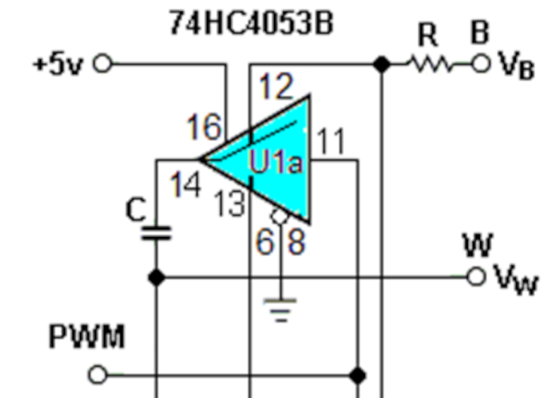
Perhaps the biggest limitation is that the PWMPot isn’t useful at even moderately high frequencies. The circuit works by driving two CMOS switches into an RC circuit. The switches’ inverted phase tends to cancel out any ripple in the signal.
The RC circuit is selected to trade response time with the precision of the final voltage output. The CMOS switches used are part of a 74HC4053B IC. While it might not solve all your digital potentiometer problems, there are cases where it will be just what you need.
We’ve looked at traditional digital pots before. If you prefer the hard way, grab a regular pot and a motor.


Interesting. I found a different approach which uses an opamp via stackexchange: https://arduino.stackexchange.com/questions/1844/how-to-emulate-an-analog-potentiometer-with-pwm/13850#13850
Both seem to need filtering to take care of the ripple.
That’s not the same thing. It’s just converting PWM to voltage with a low pass filter.
The idea of a digipot is to offer a digitally controllable variable resistance. This allows you to put the digital pot anywhere in a circuit, such as in the feedback path of an op-amp, to make a digitally controllable volume pot. You’re not just producing some voltage at the output – you’re altering some other signal voltage or current with your digitally variable resistance.
The PWMPot kinda doesn’t, because it appears to present a constant R, so it’s not a correct emulation of a digipot. What it is doing is essentially picking two input voltages A and B and switching between them rapidly, then filtering the resulting square wave down with a lowpass filter, giving you a weighted DC average between A and B chosen by the input PWM signal.
With the frequency limitations, it’s somewhat difficult to see where this would be useful.
“The idea of a digipot is to offer a digitally controllable variable resistance”
Variable voltage divider, not resistance. That would be a (digital) rheostat.
It does both. You don’t have to use both sides of the circuit.
You don’t have to use a digipot as a voltage divider. It’s technically two digitally variable resistances that have a common output. It can be a voltage divider, a rheostat (two rheostats) etc. like a real potentiometer.
It’s a potentiometer (variable voltage divider). How you connect it is up to you. You can use it as a rheostat (variable resistor), but that’s a subset of its features.
Some digital potentiometers have rheostat-only packages and those variants are labeled as such. My beef with your comment was you wrote “The idea of” instead of “one use case of”. That’s all. I’ve seen many beginners confuse potentiometers and rheostats, so that’s why I added my initial comment.
Your main point of post I agree with. That link that was shared is just a dutycycle to voltage converter. But if the supply voltage of that PWM signal is a signal, then it could function as a variable gain attenuator, not a 1to1 replacement of a potentiometer since it requires filtering and one of the terminals is connected to ground.
If you want to mince words, a potentiometer is a “three terminal resistor” with one of the terminals exhibiting variable resistance relative to the other two; in a digipot, this variable resistance is digitally controlled.
Being a voltage divider is also a subset of its features – not the defining one.
“Being a voltage divider is also a subset of its features – not the defining one.”
Correct. Like I wrote it’s a variable voltage divider, not a fixed one.
And like I wrote it was a clarification for beginners.
That’s besides the point. A potentiometer is a variable three terminal resistor first, and a voltage divider or a rheostat, or something else, second. Fundamentally, the application of a thing does not define what the thing is. It’s just that we have the habit of confusing function with substance. Because of this, we get the confusion that whatever produces a variable voltage between A and B is a “potentiometer”, but that function is actually a “mixer” – the potentiometer is a device that can do many different things.
If you want to explain it to the beginner, you would be doing a bad job explaining it in terms of some particular function rather than explaining what the thing IS. One way leads to understanding, while the other way leads to a “bag of tricks” style of knowledge without actually explaining the thing.
Known for centuries… Just Google for switched capacitor circuit or switched capacitor filter…
Btw, there are very capable analog switches in modern 74 series like 74lv.
Oh, and those usb switches/mux ICs are capable analog switches too. They are frequently used in switching IQ mixers in SDRs…
73
This does feel like a close cousin of the switched-capacitor filter.
My memory of these circuits was turning the capacitor around at the driver frequency by using four switches and an inverter.
Just checked my old Horowitz and Hill, which calls it a commutating filter, with only two switches in the block diagram, but that may work a little differently than what I remember.
I have photos of the switched-capacitor filter circuit I designed in the CU Boulder IC lab in 1984, but I no longer have the circuit designs.
Analog pots are just a FET with variable gate voltage, right?
No. The dynamic resistance of fet is dependent not only on gate voltage, but also on io pins voltage.
Years ago, before digital pots were available, we used to use DAC08 with the input signal fed to the voltage reference pin instead. Maybe it is still possible with modern low cost DACs without internal reference?
“Multiplying D/A Converters” with unbuffered access to the R/2R ladder aren’t a thing of the past, there are dozens of devices available to choose from. Even the DAC08 is still an active product.