Elliot Williams and Al Williams got together to compare notes on the most interesting posts this week on the site. As usual, there are just too many choices, so you’ll have to settle for just the few that can fit in a podcast. The guys were excited about 3D printing — both FDM and SLA — as well as a few camera projects. Ever wanted your own starship? They do, too, and you’ll hear about it along with portable radar and more.
Want to make flexible PCBs? Fill up a carbon dioxide tank? Or play Doom via regular expressions? Tune in, and you’ll find out about those stories and more.
Follow along with the links, and as always, tell us what you think about this episode in the comments! Better still, drop us a note in the mailbag, and you might hear your question on a future episode. You can record audio or send us a message, and one of the hosts will read it on your behalf.
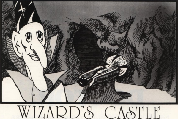
We enjoyed [Beej’s] trip down memory lane looking at a BASIC game, The Wizard’s Castle, written for the Exidy Sorcerer. It appeared in a 1980 magazine that included the title graphic above. It reminded us how, back in those days, we did things with BASIC that you shouldn’t be able to do and it often looks, today, rather cryptic.
In particular, even if you know modern BASIC, these few lines might give you a pause:
10 REM"_(C2SLFF4
40 POKE 260,218: POKE 261,1: T = USR(0): T = PEEK(-2049)
80 Q = RND(-(2*T+1))
Line 10 is a comment, but a strange one. Certainly that doesn’t matter, right? Actually, it is a key part of the action. On line 40, you can see some pokes to write directly to memory and a peek to read some memory value back. The USR function calls some machine language program. You may realize the whole thing is to get some value T to seed the random number generator in line 80.
This leads to a few obvious questions. First, how does USR know what to call? Second, where is the machine language program? The details varied by system, of course, but in this case, the program knows that location 259 has a jump instruction that USR called. So poking an address into 260 and 261 was telling USR where it should go.
But what’s at that address? Keep in mind that an old computer like the Sorcerer didn’t have megabytes of memory being swapped about by an operating system. That means that things tended to be in known places and that BASIC had to be judicious about storing source code.
For as long as humans have had writing, there’s been a need to send secret messages. It is easy to think that Enigma machines and their immediate predecessors are old tech, but they are much more recent than ancient systems used by the Greeks and Romans. Even Thomas Jefferson, one of the founding fathers of the United States, was interested in encryption and is often said to have invented the Jefferson Disk machine for encryption. The truth is, the device is probably older than Jefferson, but he certainly thought about using it for secret communications.
Simple but Effective
Thomas Jefferson was, apparently, a fan of secret messages
The idea is simple. We make a series of disks. Each disk has a number on it and, around the edge, all the letters of the alphabet. The placement of each wheel with the same number is the same, but, overall, the arrangement is random. That is, all disks marked #5 might start with XCBYG, but all disks marked with #10 could start with FAYQL. You take one set of disks, and I keep the other set.
When we want to send secret messages, we agree to arrange our disks on an axle in the same order. Jefferson used a 36-disk system, so we might agree to go left to right with the odd numbers first and then the even numbers, or any other setup that we could agree on.
Encryption
Once the wheels are in place, encryption is simple. There’s a bar across the device, and you line up your message using a wheel for each letter: ENEMYCOMESBYSEA, for example. Then you look at any different row, which will now read something crazy like: FSRSSXQCGAEEFOR (plus the random letters on the rest of the disks). That’s the message you send.
Car enthusiasts want to know how quickly they can make a quarter mile. Weightlifters are forever trying to add one more plate to the bar. Internet denizens have their own favorite number to brag about: the result from a speed test.
The ritual is familiar. Close a few browser tabs, click the big “Go” button, and watch the needle climb. Perhaps you pay for gigabit service and see 940 megabits per second, which produces a satisfied nod. Perhaps you see 299 megabits and begin obsessing over network hardware. But before you get too excited either way, try another test. There is a fair chance it will give you a different answer.
That does not necessarily mean one test is lying. “Internet speed” is not a single physical quantity waiting to be measured. A speed test measures the performance of a particular device, over a particular local connection, through a particular ISP route, to a particular server, at a particular time using a particular test method. Change any of those things and the answer can change too. Continue reading “The Need For Speed: Internet Speed Measurement (or DIY?)”→
In a recent post, I mentioned that I wanted to build some tools for a stripped-down Linux running on a 3D printer with a MIPS CPU. I had two options: build a toolchain to cross-compile, or use Zig, which, in theory, has built-in toolchains for MIPS. I had to jump through hoops to get Zig to work, and I did mention Crosstool-Ng, so you might wonder why I didn’t start there. Turns out, it had its own set of hoops to work through.
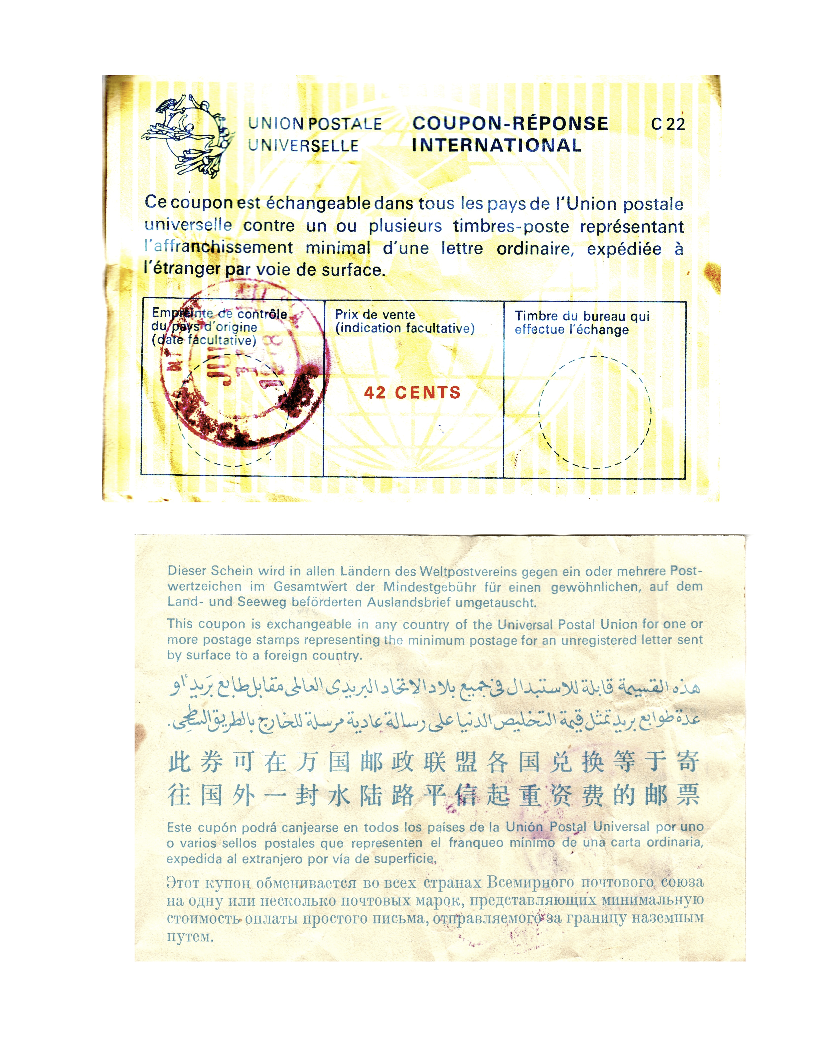
Have you ever found out that something you remember from your youth is now gone, and you didn’t even notice? If you are a certain age, you might feel that way when I deliver the news: You haven’t been able to buy International Reply Coupons (IRCs) at a US Post Office since early 2013. By the end of 2026, you won’t be able to buy them anywhere. The age of the IRC is over.
What’s an IRC?
An IRC from 1978 (public domain).
If that didn’t mean anything to you, you might be too young to remember, or maybe you just weren’t into shortwave listening or ham radio. Although there were other reasons to get IRCs, a radio hobby is the most likely reason a Hackday reader would have bought an IRC.
For radio purposes, here’s the problem. You’ve worked on your station for months, and one winter night, you finally pull in that rare station from Luxembourg. They’ll send you a QSL card to verify that you heard them. You only have to send them a letter telling them what time you heard them, what frequency, and some details about the program you heard. But they probably don’t want to pay the postage required to send hundreds or thousands of cards overseas.
While this is a radio-specific problem, you might find the same issue with pen pals or when trying to buy things from an overseas company.
SASE
If everyone were in the same country, the solution would be easy. Take a stamp, put it on an envelope that has your address on it, and stuff it in with the letter. Or, you could just drop a stamp or two in the letter you sent.
The problem is, US postage won’t help Radio Luxembourg. On the other hand, the effort required for you to buy postage that works in Luxembourg would have been a nightmare.
Enter the UPU
The Universal Postal Union is a UN agency that is effectively an association of post offices in 192 countries. Their charter is to facilitate mailing things worldwide.
The IRCs date back to 1906. The idea is you buy an IRC at your post office. You send it to Radio Luxembourg, or wherever. There, the mail person at the radio station could go to their post office and trade the coupon for enough local postage to send a surface letter worldwide.
What if you want to do something in Linux for a lot of files? [Numerator] was tired of using xarg and other ways to handle this job and created bashumerate.
Some examples in the post of the “other ways” include: