Jet Engine Tachometer Turned Into Unique CPU Utilization Meter

When you’ve got a piece of interesting old aviation hardware on your desk, what do you do with it? If you’re not willing to relegate it to paperweight status, your only real choice is to tear it down to see what makes it tick. And if you’re lucky, you’ll be able to put it to work based on what you learned.

That’s what happened when [Glen Akins] came across a tachometer for a jet airplane, which he promptly turned into a unique CPU utilization gauge for his computer. Much of the write-up is concerned with probing the instrument’s innards to learn its secrets, although it was clear from the outset that his tachometer, from Kollsman Instruments, was electrically driven. [Glen]’s investigation revealed a 3-phase synchronous motor inside the tach. The motor drives a permanent magnet, which spins inside a copper cup attached to the needle on the tach’s face. Eddy currents induced in the cup by the spinning magnet create a torque that turns the needle against the force of a hairspring. Pretty simple — but how to put the instrument to work?

[Glen]’s solution was to build what amounts to a variable frequency drive (VFD). His power supply is based on techniques he used to explore aircraft synchros, which we covered a while back. The drive uses a trio of MCP4802 8-bit DACs to generate three phase-shifted sine waves via direct digital synthesis with an RP2040. The 3-phase signal drives the motor and spins the dial, with 84-Hz corresponding to full-scale deflection.

The video below shows the resulting CPU utilization gauge — which just queries for the current load level and sends it to the RP2040 over serial — in action. It’s not exactly responsive to rapid changes, but that’s to be expected from a mechanical system. And compared to exploring such a nice instrument, it really doesn’t matter.

Continue reading “Jet Engine Tachometer Turned Into Unique CPU Utilization Meter”

Spin Me Right Round, Baby: Generator Building Experiments For Mere Mortals

How many of you plan to build a wind-powered generator in the next year? Okay, both of you can put your hands down. Even if you don’t want to wind your coils manually, learning about the principles in an electric generator might spark your interest. There is a lot of math to engineering a commercial model, but if we approach a simple version by looking at the components one at a time, it’s much easier to understand.

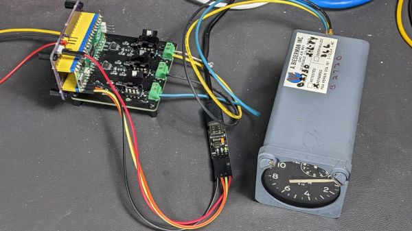
For this adventure, [K&J Magnetics] start by dissect a commercial generator. They picked a simple version that might serve a campsite well, so there is no transmission or blade angle apparatus to complicate things. It’s the parts you’d expect, a rotor and a stator, one with permanent magnets and the other with coils of wire.

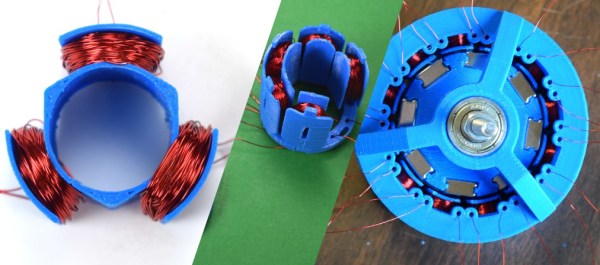
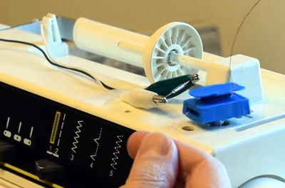
The fun of this project is copying the components found in the commercial hardware and varying the windings and coil count to see how it affects performance. If you have ever wound magnet wire around a nail to make an electromagnet, you know it is tedious work so check out their 3D printed coil holder with an embedded magnet to trigger a winding count and a socket to fit on a sewing machine bobbin winder. If you are going to make a bunch of coils, this is going to save headaches and wrist tendons.

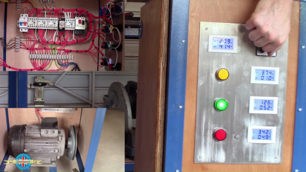
They use an iterative process to demonstrate the effect of multiple coils on a generator. The first test run uses just three coils but doesn’t generate much power at all, even when spun by an electric drill. Six windings do better, but a dozen finally does the trick, even when turning the generator by hand. We don’t know about their use of cheap silicone diodes though, that seems like unintentional hobbling, but we digress.

Making turbine blades doesn’t have to be a sore chore either, and PVC may be the ticket there, you may also consider the vertical axis wind turbine which is safer at patio level. Now, you folks building generators, remember to tip us off!

Continue reading “Spin Me Right Round, Baby: Generator Building Experiments For Mere Mortals”

Rolling Out A Slick Rotary Phase Converter

Home machinists can often find great deals on used industrial equipment, and many a South Bend lathe or Bridgeport milling machine has followed someone home. Then comes the moment to plug it in, and the new owner discovers that the three-phase plug needed to power the new beast is nowhere to be found in the shop. Thus commences the weeping and the gnashing of teeth.

Luckily, [Handmade Extreme] is ahead of the curve in terms of shop power, and built a rotary phase converter to power his machines. Industry generally runs on three-phase AC systems, mainly because three-phase electric motors are so much more efficient and compact than the equivalent single-phase motor. But residential electrical service is either split-phase or, in the UK where [Handmade Extreme] is based, single phase. A rotary phase converter is an electromechanical device that can generate the missing phases – in essence a three-phase motor that can run on one winding and generate the missing phases across the other windings. It needs some supporting control circuitry to do so, such as timers and contactors to switch the winding connections once the motor starts, plus capacitors for motor starting and for balancing the voltage across the phases. The control gear is DIN-rail mounted and neatly wired to a smart-looking control panel. Everything is housed in a sturdy enclosure that’s big enough to serve as a mobile tool cart. It’s a really nice job – watch the whole build in the video below.

If you’re interested in power distribution, we’ve got a primer that covers the basics. And if you’re in the market for machine tools, [Quinn]’s machine tool buyer’s guide will let you decide if a three-phase machine is worth the extra effort.

Continue reading “Rolling Out A Slick Rotary Phase Converter”

Smiling Robot Moves Without Wires

What could be cuter than a little robot that scuttles around its playpen and smiles all day? For the 2018 Hackaday prize [bobricius] is sharing his 2D Actuator for Micro Magnetic Robot. The name is not so cute, but it boasts a bill of materials under ten USD, so it should be perfect for educational use, which is why it is being created.

The double-layer circuit board hides six poles. Three poles run vertically, and three of them run horizontally. Each pole is analogous to a winding in a stepper motor. As the poles turn on, the magnetic shuttle moves to the nearest active pole. When the perpendicular windings activate, it becomes possible to lock that shuttle in place. As the windings activate in sequence, it becomes possible to move left/right and forward/back. The second video demonstrates this perfectly.

[bobricius] found inspiration from a scarier source, but wants us to know this is his creation, not a patent infringement. We are not lawyers.

Continue reading “Smiling Robot Moves Without Wires”