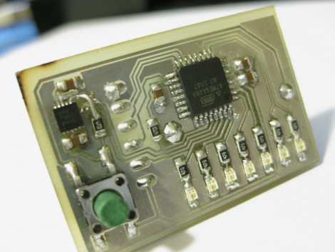
[Johannes Agricola] recently held a workshop at the Peace Mission in Goettingen, Germany where he shared his RGB LED flowers. The small round PCB hosts an ATmega88 microcontroller which is running the V-USB stack so that the unit can be controlled by a computer. Each flower blossom is an RGB LED connected with four enameled wires which, when twisted together, make up the stem of the flower. [Johannes] took tons of pictures during the assembly while offering soldering advice along side the illustrations. The PCB is single-sided helping make this a great project for someone trying out surface mount component soldering for the first time. Or if you want something a little more free-formed try out this lemon-juice powered LED flower.
LED Hacks1841 Articles
512 LED Cube
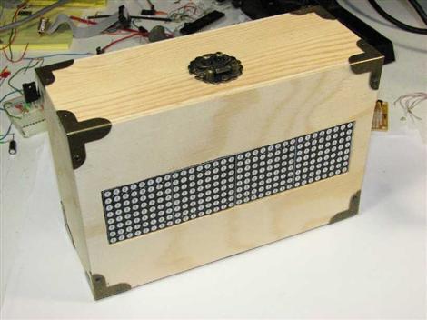
Get out the soldering iron and clear your schedule, it’s going to take you a while to assemble this 8x8x8 LED matrix which contains a total of 512 LEDs. We’ve looked in on a 3x3x3 cube, and [Chr], who is responsible for this one, has assembled a 4x4x4 cube before, but this one is quite a leap in complexity. It isn’t just physical assembly problems that increase with scale, you’ll need to consider a power supply too since one layer of a 3x3x3 cube would need at 90 mA, but a single layer of the cube above requires 640 mA to light all of the diodes. Multiplexing is handled per-layer, controlled by ICs which share 8 data lines and are latched by a shift register. This means the display only requires 11 microcontroller pins for addressing. It is striking how well [Chr] explains the design process, and how cleanly he builds the driver circuits on protoboard. There’s a lot to look at and a lot to learn, not to mention the stunning results which can be seen in the video after the break.
Light Testing Facility Tour
Here’s a fun video tour of a light testing facility. Admittedly, its not as fun as watching cell phones get abused, but it is interesting. The video is only about 6 minutes long, and is mostly a narrated slide show, but is full of information. There’s plenty to learn about the bulbs themselves, as well as the testing procedures. What you can see above is a box full of LED testing units.
Accidental LED Fabrication
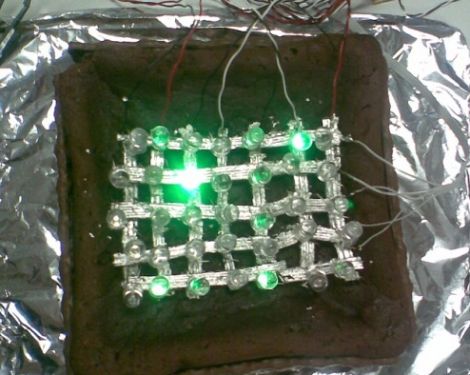
[Grenadier] had a piece of silicon carbide sitting around that he planned to use when making a primitive diode called a Cat’sWhisker Diode. While probing he noticed that one of the crystals threw off a bit of light. He popped it off and used JB Weld to attach it to a brass plate. The peculiar thing is that it generates light when power is run through it both forward and reverse biased. So what’s going on here? According to an informed discussion on the phenomenon there’s actually a pair of diodes in series but with their polarity reversed.
LED Lighthouse Simulator
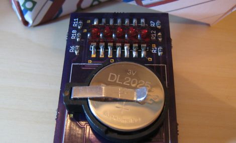
This Christmas [Bill Porter] decided to show his parents that those college dollars were well spent. He upgraded the custom lighthouse light which he originally designed in high school for their garden fountain. He even went so far as to craft some retail-worthy packaging for the gift.
We think it’s a wonderful design, on a custom PCB and based around an ATtiny85. A real lighthouse has a spinning lens to aim the beam of light. When the lens sweeps across your viewpoint there is a sudden flash and he’s recreated that effect using PWM. Take a look at the video after the break and you’ll see what we mean.
Also, during development he was plagued by a startup glitch which we got majorly sidetracked reading about. Continue reading “LED Lighthouse Simulator”
Didn’t See The Lunar Eclipse, Make One!
Last night was a lunar eclipse meaning that most people would have been out gazing up at the sky watching it. For some the eclipse evaded them using cloud cover, but instead of giving up, they got innovative. [Garrett] decided to build a moon simulator to keep track of the eclipse using a few spare parts and some quick code. The parts that were required for this project includes an Arduino UNO, a singular ShiftBrite Shield, a ShiftBar, ChronoDot and a Satellite Module 001. This is the perfect project for the Arduino to be used in because he had to toss it together very quickly and it is meant to be a temporary solution. If he were to make this permanent, we would guess that he would make a smaller and more cost effective version of the electronics. He documents his experience on Macetech.com in more detail and the outcome is pretty amazing. Code is yet to be posted but hopefully it is forthcoming soon as well as a video of the simulator working.
Hacked LED Christmas Lights
[Robert] wanted more out of his GE Color Effects G-35 LED Christmas lights. He reverse engineered and then hacked the protocol the lights use to communicate so that he can control each bulb. A 26-bit frame contains a 6-bit address, an 8-bit brightness value, and a 12-bit color value. The daisy chain topology of the data bus allows for modular bulbs with addresses enumerated during the startup of the string of lights. With this information, a 5 volt capable microcontroller is able to control a whole string of these lights with a refresh rate of up to 24Hz. In this case, [Robert] used an ATtiny13A microcontroller to control the string of lights. You can see a video of them in action after the break.
Also taken apart and analyzed, were the wireless transmitter and receiver that came with the lights, revealing a cheap ISM band receiver and transmitter module pair. Perhaps they will be useful for another project. We look forward to seeing people put these hacked lights to use throughout the year.
[via Make]