It’s a skill that radio amateurs pick up over years but which it sometimes comes as a surprise to find that is not shared by everyone, the ability to casually glance at an antenna on a mast or a rooftop and guess what it might be used for. By which of course I mean not some intuitive ability to mentally decode radio signals from thin air, but most of us can look at a given antenna and immediately glean a lot of information about its frequency and performance. Is this privileged knowledge handed down from the Elmers at the secret ceremony of conferring a radio amateur’s licence upon a baby ham? Not at all, in fact stick around, and I’ll share some of the tricks. Continue reading “Identify That Antenna By Sight”→
Direction-finding, or fox hunting, is a popular activity in ham radio circles where a group of people armed with radios attempt to locate a broadcasting source. Besides being a hobby for amateurs, it’s also a necessary tool in the belt of regulators who are attempting to track down violators of the air space. There are a lot of ways to figure out the precise location of a radio transmission, but this one manages to pull it off using both a boat and a Steam Deck, each armed with a software-defined radio.
This project comes to us from [Aaron] who is well known in the amateur radio circles for his SDR-focused Linux distribution called DragonOS; which has all the tools needed for a quality SDR experience, in this case KrakenSDR and DF Aggregator. He’s loaded everything up on a Steam Deck and left that in a secure location on the shore of a lake, while he carries second device with the same software with him on a boat. With the two devices listening for a specific signal, he’s able to quickly zero in on his friend on the shore who is broadcasting on the 70 cm band thanks to the help of all of these software packages.
While ham radio isn’t always known for being a youthful and exciting activity, the advent of software-defined radio and other digital modes seem to be shaking things up in that world. Certainly speeding around a lake on a boat is fun on its own as well, and a fox hunt like this can be done with something as small and simple as a Raspberry Pi too.
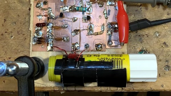
For over a century now, radio amateurs have made tuned circuits using a coil of wire and a variable capacitor. In recent decades the supply of variable capacitors has dwindled, as SDR technology has supplanted the traditional tuning capacitor. No more tuned circuits for the radio amateurs? Not quite, as [Bill Meara N2CQR] shows us in the video below the break by making variable inductors using permeability tuning. This is hardly high-tech, the major component is as simple as a glue stick.
A permeability tuned inductor has a core that is moved in and out of its center by means of a screw. A glue stick has a glue core on a lead screw from a knob at its end, so an old glue stick with the glue replaced by a ferrite ring makes a reasonable permeability tuned former. The coil is wound on its outside, and when assembled into an oscillator it gives a useful tuning range. This is hardly a new idea as permeability tuning could be found in car radios and TV tuners among other applications back in the day, but it’s still a good trick to bear in mind.
We’ve featured plenty of Bill’s videos before here at Hackaday, most recently tracking down an unusual early TV.
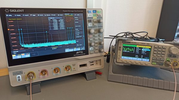
A casual understanding of how AM radio works is pretty easy to come by, and standard FM is only a little more complicated. Things can go off the tracks a bit with stereo FM, though — figuring out how they squeeze two separate audio tracks onto one radio signal is a bit of a head-scratcher. In that case, wrapping your head around the concept might be helped by mocking up a stereo FM signal with an arbitrary waveform generator and a little bit of Python.
Not that [Sebastian] of Baltic Lab was unfamiliar with multiplex FM theory, mind you. As he explains it, his goal was to generate a valid stereo FM signal with a different pure tone on each channel, 700 Hz on the left and 2,200 Hz on the right. Luckily, [Sebastian] has a nice AWG, the Siglent SDG1032X, which has an Ethernet connection that can be used to control it remotely along with PyVISA, a Python package for controlling instruments using the Virtual Instrument Software Architecture protocol.
The meat of this project, and what really helps drive home the concept of putting multiple audio signals onto an FM signal, lies in the Python code that generates the component parts. [Sebastian] does a great job explaining how he programatically generates the sum and difference signals along with the 19 kHz pilot tone, and puts them all together into one waveform. The output of the program is used to generate a series of values that are sent to the arbitrary waveform generator, which outputs the desired FM signal. Looking at the output on a spectrum analyzer, the two audio tones are clearly visible, as are the attenuated pilot tone and some other spikes a little further up.
Just add an antenna to the setup and you’d have the world’s dullest FM radio station — but at least it’d be in stereo. Or if you want to check out the origin story for FM radio, we’ve got something for that too.
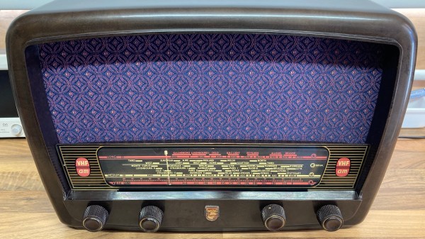
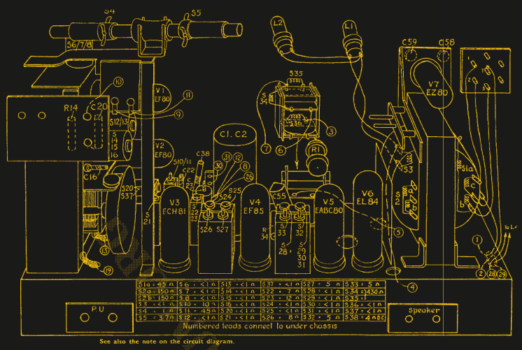
Ever wanted a good, good look at the insides of a 1950s radio, along with fantastic commentary on the internals and the purpose of various components? Then don’t miss [Adam Wilson]’s repair and restoration of a 1956 Philips 353A, a task made easier by a digitized copy of the service manual. [Adam] provides loads of great pictures, as well as tips on what it takes to bring vintage electronics back to life. What’s not to like?
Vintage electronics like this are often chock-full of components that deteriorate with age, so one doesn’t simply apply power to see if it still works as a first step. These devices need to be inspected and serviced before power is ever applied. Even then, powerup should be done with a current-controlled source that can be shut down if anything seems amiss.
Thank goodness for high quality, digitized service manuals.
Devices like these largely predate printed circuit boards, so one can expect to see plenty of point-to-point soldering. Vacuum tubes did much of the hard work, so they are present instead of integrated circuits and transistors. Capacitors in the microfarads were much larger compared to their modern equivalents, and paper/wax capacitors (literally made from rolled-up paper covered in wax) handled capacitances in the nanofarad range instead of the little ceramic disk caps of today.
One thing that helped immensely is the previously-mentioned Philips 353A service manual, which includes not only a chassis and component layout, but even has servicing procedures such as cord replacement for the tuning dial. Back then, a tuning dial was an electromechanical assembly that used a winding of cord to rotate the tuning capacitor, and replacing it was a fiddly process. If only all hardware was documented so well!
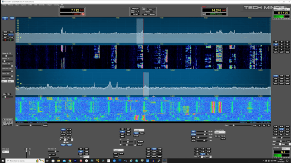
If you’ve noticed the TRX-DUO software-defined radio transceiver, you might have wondered how it stacks up to other choices like Red Pitaya or HackRF. [Tech Minds] obliges with a review of the Red device in the video below.
While this unit isn’t inexpensive, it also isn’t as expensive as some of its competitors. Sure, you can pick up an RTL-SDR dongle for a fraction of the price, but then you miss out on transmitting. The device is pretty powerful compared to a cheap software defined radio:
Frequency: 10 kHz to 60 MHz
CPU: Zynq SoC with a dual-core ARM Cortex A9
RAM: 512 MB
OS: Linux
Connectivity: Ethernet and USB connectivity (WiFi with a dongle)
ADC: 16-bit at 125 MS/s (2 channels)
DAC: 14-bit at 125 MS/s (2 channels)
The board boots off an SD card and there are several to choose from. The video shows two different images. One has a number of applications that run on the device and will also run on a Red Pitaya. The device shows a browser menu with various options and the result is quite impressive. Using the box as a WSPR beacon, it was heard fairly well given the low output power. It was, however, able to hear the world easily.
You can get a less capable Red Pitaya model for about $100 less than the going price. However, for something comparable, you will pay more for the Red Pitaya and — depending on capabilities — perhaps a lot more, although you do get more capability for the increased price.
You can do a lot more with a transmitting SDR — having both transmit and receive opens up many new projects. Of course, canned applications are great, but if you get one of these, you are going to want to try GNU Radio.
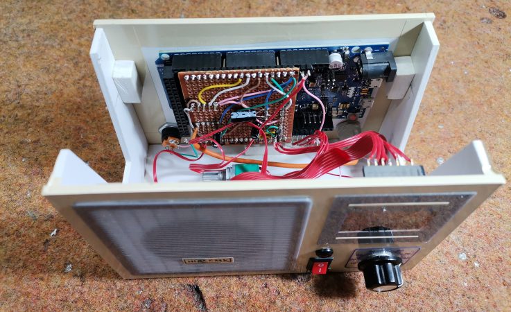
Older hackers will remember that a crystal set radio receiver was often one of the first projects attempted. Times have changed, but there’s still something magical about gathering invisible signals from the air and listening to the radio on a homemade receiver. [mircemk] has brought the idea right up to date by building an FM radio with an OLED display, controlled with a rotary encoder.
The design is fairly straightforward, based as it is on another project that [mircemk] found on another site, but the build looks very slick and would take pride of place on any hacker’s workbench. An Arduino Due forms the heart of the project, controlling a TEA5767 module, an SH1106 128×64 pixel OLED display and a rotary encoder. The sound signal is passed through an LM4811 headphone amplifier for private listening, and a PAM8403 Class D audio amplifier for the built-in loudspeaker. The enclosure is made from PVC panels, and accented with colored adhesive tape for style.
It’s easier than ever before to quickly put together projects like this by connecting pre-built modules and downloading code from the Internet, but that doesn’t mean it’s not a worthwhile way to improve your skills and make some useful devices like this one. There are so many resources available to us these days and standing on the shoulders of giants has always been a great way to see farther.