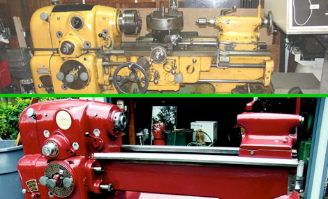
Frankenstein’s Lawnmower

[phantompinecone] has an electric mower that worked great for about 4 seasons, and then the battery started to die. A replacement was installed but it started being a pain after the first season. Since the battery was brand new (and probably costly too) there must be something else.

Checking the brushes, which were fine, the next logical place was the switch.These mowers are just a battery, motor, and switch. Yanking it apart there was indeed a problem, they were chewed up and corroded, not allowing full electrical contact. So [phantompinecone] replaced the simple mechanical switch with a MOSFET.

Electrically there is an IRF1405 MOSFET, some resistors to pull signals around and a couple diodes to A) keep the back emf from the motor in check, and B) drop the voltage going into the fet from 24volts to 12. Problem solved, and the motor should not have anymore trouble caused by a junked up switch.

Simple IR Bounce Tachometer

[Rajendra Bhatt] writes in to let us know about a nice simple IR bounce tachometer. The project uses a startUSB for PIC board and a 16×2 character LCD with a very basic Infrared bounce circuit.  Measuring either a reflective or non reflective spot in the rotating object, in this case a bit of white paper, the micro is supposedly capable of measuring up to 99,960 RPM (we think the paper might fly off at this point) with a resolution of 60 RPM. This is the same concept as a beam-break style tachometer but keeps all your electronics on one end of the spinning hazard.

The article also goes into detail about setting the PIC18F2550’s Timer0 register to enable 16-bit resolution.  The PIC is configured to turn on the infrared LED for one second, measure the number of pulses (through timer registers), and multiply that value by 60.  We would be more careful with the TMR0H and TMR0L counters as they have to be read and written in a certain order to preserve their values, but you’d need to be measuring upwards of 15,360 rpm to run into that error.

It is a quality writeup for anyone interested in learning about the start USB for PIC board, tachometers, or a new project. Thanks [Raj]!

Auxiliary Battery Pack For Field Operations

portable_battery_pack

Ham operator [Ken – wa4mnt] wrote us to share a small project that he uses nearly every time he goes out in the field. His portable sealed lead acid battery pack (PDF) always ensures that he has a 12v power source at his fingertips, both for fun as well as in emergency situations.

The battery pack is pretty simple, and includes a 12v, 17ah battery strapped into a light aluminum chassis which he fabricated. The battery is secured with zip ties, so it can easily be swapped out or replaced without much fuss. The frame also sports a tiltable 4w, 17.5v solar panel that keeps the battery topped off and ready to go at all times. He stuck a voltmeter to the top of the battery to keep an eye on things, and he employs a 10A fuse to make sure he doesn’t fry any sensitive radio components should something go wrong.

The battery pack is pretty compact when you think about it, and we imagine it would be great to have on hand for a wide array of outdoor activities. Even if you’re not into Ham field operations, it’s hard to argue with its usefulness during power outages.

[Ken] doesn’t appear to have any published plans for the chassis or the electronic portion of the pack, but we’re pretty sure he would share if asked.

Full-featured Battery Tester Puts Them Through Their Paces

When working on battery-dependent projects you want accurate performance information where a datasheet may not be available. [E. Lelic] set out to build a device that would meter internal battery resistance but ended up with a bench tool that can do much more than that.

A PIC 16F88 microcontroller takes center stage on the meter, taking voltage level readings, monitoring a DS1820 temperature sensor, and controlling an LM2575 step-down regulator. The components provide functionality for measuring Lithium Ion, Lithium Polymer, Nickel Cadmium, Nickel Metal Hydride, and Alkaline batteries. It is capable of fully discharging and fully charging the batteries, measuring time and power consumption during this cycle, and monitoring temperature changes for the NiMH and NiCad versions.

Look for the little red ‘Download’ icon at the bottom of the post linked above. That archive includes a schematic (which we’ve also embedded after the break), board layout in .LAY format, and a HEX firmware file.

If you enjoyed this build you might want to look at this other battery capacity tester.

Continue reading “Full-featured Battery Tester Puts Them Through Their Paces”

Buying A Laser Cutter From China

We here at Hackaday have been pining over these cheap laser cutters on the e-bay. They are, however, just outside of the price range to make them worth ponying up for.  [Stephen Hobley] however seems to have taken one for the team in his three part series, and is allowing us to live vicariously through is experiences.

Not surprisingly the price point leads to the potential for headaches. The units ship directly from China, and see their fair share of rough handling from package carriers. Broken/misaligned laser tubes are not uncommon (replacement tubes are prevalent). Shockingly the laser tube managed to survive the seven thousand mile journey! That only leaves a couple crucial modifications and careful cleaning and aligning to get the unit up and running. You didn’t think it would be that easy, did you?

To top off all the modifications adjustments and cleaning steps [Stephen] found (in part three) that his controller board was on the fritz. With a new one on the way from China, [Stephen] is debating either reverse engineering the included controller board or coming up with his own CNC solution. We could suggest quite a few alternate solutions ourselves.

We will be glued to [Stephen]’s blog for updates.

Stick around for a video of what we all really want to see, a laser burning stuff.

Continue reading “Buying A Laser Cutter From China”

Variable Capacitance/reistance Switch Box Has You Covered

variable_cap_resistor_box

While working on electronics projects, it’s often necessary to test out different capacitance or resistance values as things are moving along. Depending on what you are testing, this can be a tedious process even when using a breadboard. Instructables user [mattthegamer463] recently built a very useful device that would help out in these situations, and would likely be a welcome addition to any Hackaday reader’s workbench.

His variable resistor/capacitor box makes it easy to test out any number of different resistance or capacitance values with a simple turn of a knob. He wired up a pair of pots to provide a wide range of resistance values, being sure to add a low-resistance safety as well as safety override switch for those of you who like to have things blow up in your face live dangerously. A set of 22 capacitors were wired up on a piece of perfboard, each of which can be selected using a pair of knobs. He added a simple switch to allow the capacitors to be toggled between parallel and series orientations as well.

[Matt] did a wonderful job here – this is a great project that can be customized in a multitude of ways to fit almost anyone’s specific needs.

Using Your PC As A Simple Signal Generator

dc_offset_circuit

[Debraj] needed a simple signal generator for a project he was working on, but didn’t have one handy. He found that the easiest and cheapest way to get clean, reliable signaling was by using something that was already sitting on his desk – his PC.

He found that the tone generator built into Audacity was quite useful, at least for generating waveforms at less than 20 KHz or so. Upon plugging his scope into his sound card’s audio jack, he observed that the PC had good frequency fidelity, though it required an additional DC offset as most cards are built to remove that offset from the waveform.

Using a LM358 as a non-inverting summing amplifier, he was able to apply a steady DC offset and generate usable signals for his micro controller projects. A schematic for his offset circuit is available on his site, should you wish to build one of your own.

[Debraj] also notes that though Audacity is a cheap free way to generate simple signals, any number of complex signals can be generated using MATLAB if you happen to own a copy.