Bluetooth Communications For Android Devices Via Processing

[Oscar] shows us how to use a Processing sketch for Android to communicate with Bluetooth devices (translated). It turns out this is easier than you might think. Processing and Android are both closely related to Java, and you can just import the Android libraries that deal with Bluetooth within the Processing sketch. That makes it easy to enable the Bluetooth modem when the sketch is launched, and manages connecting with devices as well as sending and receiving data.

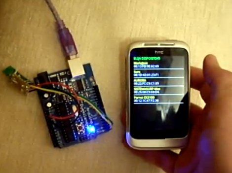
For this example [Oscar] is using an Arduino with a Bluetooth module as a test device. His sketch first shows what devices are available, then connects to the one you select from the list. The 11 lines of Arduino code transmit a value via the serial port, and listens back for a command to toggle the LED on pin 13. [Oscar] takes time in his tutorial to show us how each step of the Processing sketch is assembled, instead of only posting the finished code.

[Thanks Sara]

Python On A Microcontroller

The team at LeafLabs was looking for something cool to do with their new ARM development board. [AJ] asked if anyone had ever played around with Python, so [Dave] cooked up an implementation of PyMite and put it on a Maple board. While the writeup is only about blinking a LED with a microcontroller, they’re doing it with Python, interactively, and at runtime.

The build uses the Maple Native board the team is developing. The board has a 32-bit ARM chip with 1 Meg of RAM – more than enough horsepower to run PyMite. The tutorial for putting PyMite on a Maple is up on the LeafLabs wiki.

PyMite is theoretically able to control every pin on the Maple Native and do just about everything a regular Python distro can do. The LeafLabs team is still working on the necessary libraries for their board (although we don’t see anything on the Google code page), so right now only blinking the LED is supported. Still, it’s pretty cool to have Python in your pocket.

Barebones PIC RFID Tag

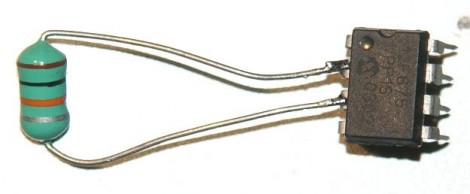
An inductor and 8-pin microcontroller are all that make up this barebones RFID tag. You might have done a double-take when first seeing the image above. After all, there’s nothing hooked up to the power and ground pins on the chip. As [Ramiro Pareja] explains in his post, the power is actually supplied via the I/O pins to which the inductor is soldered. It seems that each I/O pin has a parasite capacitor and a pair of clamping diodes inside the chip. When the AC current that is induced by the magnetic field of the RFID reader hits those pins, the capacitors charge and the clamping diodes form a bridge rectifier. This results in power being injected into the chip, which turns around and sends the RFID code back through the inductor.

This isn’t the first time that we’ve seen this concept. We featured a hack that is exactly the same except it used an AVR chip. This one uses a PIC 12F683 but should work with just about any 12F or 16F model. The code is written in Assembly and shouldn’t need any changes for different hardware. [Ramiro] does talk a bit about adding a decoupling capacitor to Vss and Vdd, as well as a tuning capacitor to the two I/O pins used above to help make the device a little more robust. But, as you can see in the video after the break, it works just fine without them.

Continue reading “Barebones PIC RFID Tag”

Voxel Shield Makes Driving LED Cubes Easy

voxel_shield_led_cube

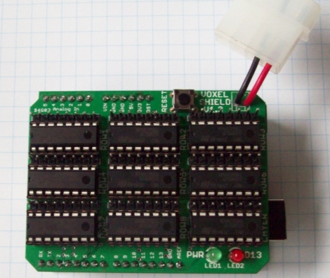
An Arduino can handle running a small LED cube on its own, but if you’re planning on building something big, eventually you are going to run out of pins. For something like an 8x8x8 cube, odds are you will have to turn to shift registers to get the job done. While you could design a breakout board full of shift registers on your own, [Connor] has done the work for you and produced an easy to use Arduino LED cube shield.

He calls his creation the Voxel Shield, and it incorporates 9 SN74LS595N shift registers and an external power plug for all of your LED cube needs. The shield can handle addressing up to 512 LEDs, making it an easy way to drive an 8x8x8 cube or even a 64×8 LED matrix.

It’s a nice clean and compact way to drive a large number of LEDs, so if you have the need, be sure to swing by his site – he has made his schematics and board layout files available to all comers.

[Thanks, Thomas]

Capacitive Sensing Tutorial

[Bertho]’s submission for the 74xx logic contest is really impressive. He designed a capacitive sensing touchpad using only 74xx and 40xx logic chips. We’re impressed with the build and his writeup is one of the best resources we’ve ever seen for capacitive sensing.

There are two ways to go about designing a capacitive touchpad. The first option is put a voltage through an RC circuit. Measure the voltage-time curve, and you have a measure of the capacitance of the circuit. The second method is setting up an RC circuit to change polarity after a threshold for C has been reached. Microprocessors only use one of these methods (AVR uses the first, PIC uses the second), but [Bertho] decided to implement both methods for unknown reasons we still respect.

The circuit [Bertho] designed has a 30MHz clock using only 74xx logic chips, an amazing feat in itself. An 8×8 channel panel was fabricated and the whole build connects to a computer over RS-232.

The finished build is good enough has 64 points of resolution and is able to detect proximity very well. The touchpad is even able to recognize when a pen is placed on the panel. Check out the video after the break for the walk through and demo of this amazing build.

Continue reading “Capacitive Sensing Tutorial”

The Water Calligraphy Tricycle

Many westerners visiting or living in China may observe the art of “water calligraphy” and some may even try to imitate it. However, media artist [Nicholas Hanna] decided to take a totally new approach and make his own water painting machine.

Someone less creative would have devised some imitation of a human, but [Nicholas] decided to totally rethink the process in the form of a tricycle.  Using 16 PC-controlled water solenoids, this tricycle is turned into a sort of moving dot matrix printer. It doesn’t have the same sort of grace that the traditional Chinese art does, but it’s quite a bit faster, so if you want to get your message out, this might have some practical applications.

The post doesn’t go into the electronics, but the video after the break includes some close-ups and video of [Nicholas] assembling the device. If you happen to be in china, his tricycle is part of an event for “Beijing Design Week” at the Northern Electric Relay Factory until October 3rd.

Continue reading “The Water Calligraphy Tricycle”

Over-the-air FM Radio Gains Internet Control

[Old bit collector] is giving up control of his radio dial to the Internet. He combined a couple of Parallax products which now allow him to tune, adjust volume, and toggle the power for an FM radio receiver.

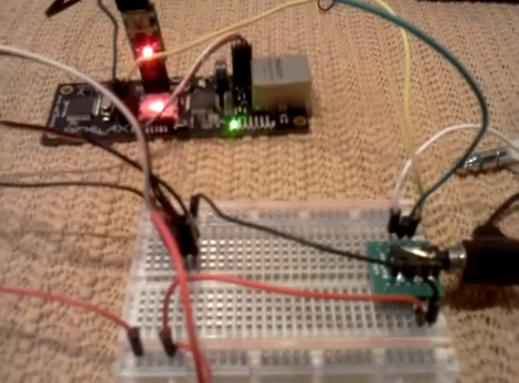
The setup is pretty simple. An FM receiver module is mounted in the breadboard seen above which helps to break out its control pins. Those are connected to a Parallax Spinnarette web server board. It’s auxiliary I/O pins are controlled via a web interface that he set up and plans to operate with the browser on his Android phone. But as you can see after the break, any web browser works as long as you know the correct address.

This is pretty good if you’re on a quest to make everything controllable from your smart phone. But we would love to use the concept to make our own streaming radio. You’d be able to tune in to all of your local stations from anywhere in the world.

Continue reading “Over-the-air FM Radio Gains Internet Control”