For a few years now, the Rigol DS1052E has been the unofficial My First Oscilloscope™. It’s cheap, it’s good enough for most projects, and there have been a number hacks and mods for this very popular scope to give it twice as much bandwidth and other interesting tools. The 1052E is a bit long in the tooth and Rigol has just released the long-awaited update, the DS1054Z. It’s a four-channel scope, has a bigger screen, more bells and whistles, and only costs $50 more than the six-year-old 1052E. Basically, if you’re in the market for a cheap, usable oscilloscope, scratch the ~52E off your list and replace it with the ~54Z.
With four channels of input, [Dave Jones] was wondering how the engineers at Rigol managed to stuff two additional front ends into the scope while still meeting the magic price point of $400. This means it’s time for [Dave] to reverse engineer the 1054Z, and give everyone on the Internet a glimpse at how a real engineer tears apart the worth of other engineers.
The first thing [Dave] does once the board is out of the enclosure is taking a nice, clear, and in-focus picture of both sides of the board. These pictures are edited, turned into a line drawing, and printed out on a transparency sheet. This way, both sides of the board can be viewed at once, allowing for a few dry erase marker to highlight the traces and signals.
Unless your voyage on the sea of reverse engineering takes you to the island of despair and desoldering individual components, you’ll be measuring the values of individual components in circuit. For this, you’ll want a low-voltage ohms function on your meter; if you’re putting too much voltage through a component, you’ll probably turn on some silicon in the circuit, and your measurements will be crap. Luckily, [Dave] shows a way to test if your meter will work for this kind of work; you’ll need another meter.
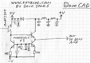
From there, it’s basically looking at datasheets and drawing a schematic of the circuit; inputs go at the left, outputs at the right, ground is at the bottom, and positive rails are at the top. It’s harder than it sounds – most of [Dave]’s expertise in this area is just pattern recognition. It’s one thing to reverse engineer a circuit through brute force, but knowing the why and how of how the circuit works makes things much easier.
Continue reading “How To Reverse Engineer, Featuring The Rigol DS1054Z”



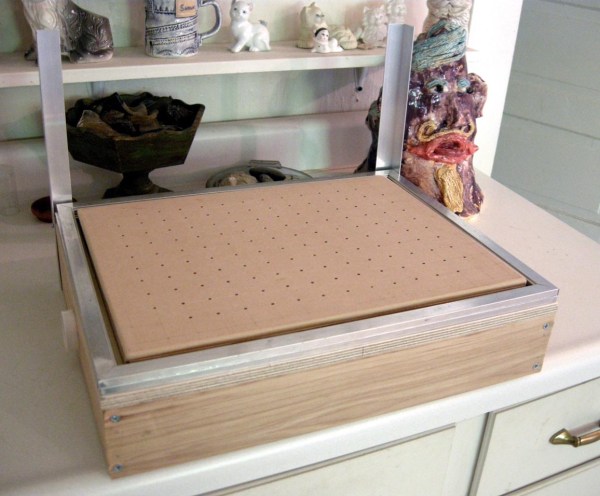
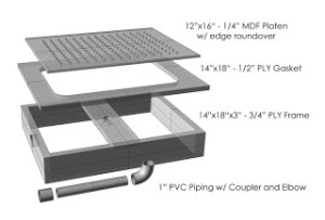 There is a two-pronged attack to keep the costs down on this project. First, the frame is made from readily available materials that you probably have kicking around in your wood scrap bin. The sides of the frame are 3/4″ plywood and the hole-filled top is made from 1/4″ MDF. A piece of PVC pipe connects the chamber below the top piece of MDF to a shopvac. The shopvac pulls the air down through the top’s holes; think reverse air hockey table.