The 555 can do anything. OK, that’s become a bit of a trope in our community, but there is quite a lot of truth behind it: this little timer chip is an astonishingly versatile component.
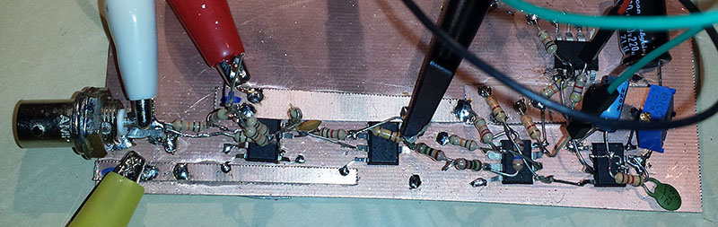
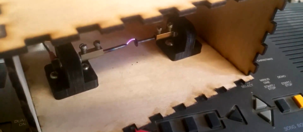
[Alexander Lang] has added another achievement to the 555’s repertoire, he’s used one in the creation of a plasma speaker. Working at Hackspace Manchester, he’s used the 555 as a pulse-width modulator that drives a flyback transformer through a MOSFET, which feeds a spark gap mounted in a lasercut enclosure. The results maybe aren’t yet hi-fi, but it works, and is very audible.
We’ve been following this project for a while, as he’s updated his progress through several iterations. From initial design idea through PCB and enclosure design, to a first working prototype and some audio refinements, and finally this latest post with the spark gap in its enclosure. He is still refining his speaker, so there is more to come
In the video below the break he demonstrates his pulse width modulator, and tests the device using a keyboard as an input.