POV Globe Display Spins Up Full Color Tupac

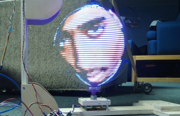
Persistence of vision projects were once all the rage, judging by a quick review of the literature here on Hackaday. They’ve tapered off a bit lately, but this impressive full-color globe display might just kick-start some new POV projects.

Built as a final project for an EE course, [Evan] and [Kyle]’s project is more about the control electronics and programming than the mechanical end of the build. Still, spinning a 12″ ring of 1/4″ thick acrylic with a strip of APA102 LEDs glued to the edge takes some thoughtful engineering. While the build appears sturdy, [Evan] does admit to a bit of wobble under full steam, which was addressed by adding some weight to the rig. We wonder if mounting half the LEDs on each side of the ring to balance the forces wouldn’t have worked better. True, it would have complicated the coding for the display, but maybe that would have been good for extra points. In any case, the display turned out well and the quality of the images is great. And as an aside: how awesome is it that we live at a time when you can order a six-circuit slip-ring for a project like this for less than $20?

It’s the end of the semester and we love seeing the final projects that have just made it across the finish line. This globe is one, yesterday we saw a voice-controlled digital eye exam, and if you have or know of a final project, don’t forget send us the link!

If POV globes are your thing, be sure to set the Hackaday WABAC machine a few years and check out this Death Star design from 2012 or this globe from 2010.

1768 LEDs, Because 96 Just Wasn’t Enough

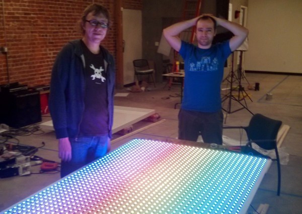
Some people would look at a massive 6’x4′ LED matrix hanging on the wall playing animations and be happy with the outcome. But [Ben] just isn’t one of those people. The original FLED (Fantastic LED thingy) was eight rows of twelve addressable LEDs for a total of 96 pixels. This spring he upped his game and retrofitted the display with 1768 LEDs.

It wasn’t simply an issue of restlessness, the original build suffered from LEDs dying. We actually featured it for that reason as a Fail of the Week.  This is not strictly a hobby project, it’s hanging on the wall in the Supplyframe offices, so pulling it down frequently to fix broken parts is not ideal.

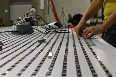
fled-reborn-LED-layoutTo make FLED more reliable [Ben] sourced strips of the new APA102 LEDs which we looked at back in December. They use an SPI bus instead of the bizarre timing scheme of the WS2812. At first glance you’d think this would mean easier assembly compared to soldering both sides of each of the original 96-pixels. These do come in strips, but laying out 52×34 still means soldering to the ends of each row.
A lot of love went into making sure those rows were laid out perfectly. A sheet of white foamed PVC serves as the substrate. There is grounding braid on either end of the rows, one is the voltage bus, the other is ground. It fits the original enclosure which is acrylic and does a great job of diffusing the light. I’ve seen it in person and it looks pretty much perfect!

It’s not just the physical layout of this many pixels that is a challenge. Pushing the data to all of them is much harder than it was with 96. [Ben] transitioned away from RaspberryPi. He considered using a Teensy 3.1 and ESP8266 but the WiFi of these cheap modules is far too slow to push frame information from a remote box. In the end it’s a BeagleBone Black that drives the reborn display. This is a great choice since there’s plenty of power under the hood and a traditional (and much faster) WiFi dongle can be used.

Don’t miss the animation demos found after the break.

Continue reading “1768 LEDs, Because 96 Just Wasn’t Enough”

Digging Into The APA102 Serial LED Protocol

[Tim] got his hands on some APA102 RGB LEDs, which are similar in function to the common WS2812 addressable LEDs seen in many projects we’ve featured. The advantage of APA102 LEDs is that they don’t have the strict timing requirements of the WS2812. These LEDs are controlled with a SPI bus that can be clocked at any arbitrary rate, making them easy to use with pretty much any microcontroller or embedded system.

After working with the LEDs, [Tim] discovered that the LEDs function a bit differently than the datasheet led him to believe. [Tim] controlled a strand of APA102 LEDs with an ATtiny85 and connected a logic analyzer between some of the LEDs. He discovered that the clock signal of the SPI interface isn’t just passed through each LED, it actually looks like it’s inverted on the output. After some investigation, [Tim] found that the clock signal is delayed by a half period (which looks like an inversion) before it’s passed to the next LED. This gives the next LED in the strand enough time for data on the data line to become valid before latching it in.

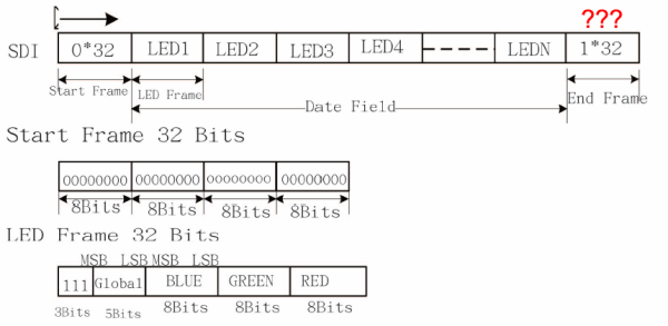
Since the clock is delayed, [Tim] discovered that additional bits must be clocked as an “end frame” to generate clock signals which propagate the remaining data to the end of the strand. Although the datasheet specifies a 32-bit end frame, this only works for strings of up to 64 LEDs. More bits must be added to the end frame for longer strands, which the datasheet doesn’t even mention. Check out [Tim]’s post for more information, where he walks you through his logic analysis of the APA102 LEDs.