Behind The Pin: Logic Level Outputs

There is one thing that unites almost every computer and logic circuit commonly used in the hardware hacking and experimentation arena. No matter what its age, speed, or internal configuration, electronics speak to the world through logic level I/O. A single conductor which is switched between voltage levels to denote a logic 1 or logic zero. This is an interface standard that has survived the decades from the earliest integrated circuit logic output of the 1960s to the latest microcontroller GPIO in 2018.

The effect of this tried and true arrangement is that we can take a 7400 series I/O port on an 8-bit microcomputer from the 1970s and know with absolute confidence that it will interface without too much drama to a modern single-board computer GPIO. When you think about it, this is rather amazing.

It’s tempting to think then that all logic level outputs are the same, right? And of course they are from a certain viewpoint. Sure, you may need to account for level shifting between for example 5V and 3.3V families but otherwise just plug, and go, right? Of course, the real answer isn’t quite that simple. There are subtle electrical differences between the properties of I/O lines of different logic and microcontroller families. In most cases these will never be a problem at all, but can rear their heads as edge cases which the would-be experimenter needs to know something about.

Continue reading “Behind The Pin: Logic Level Outputs”

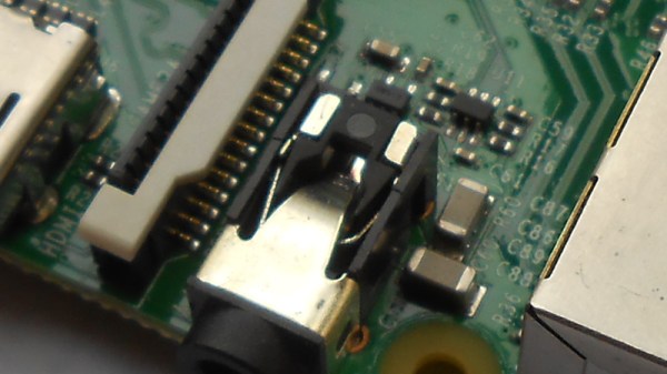
Behind The Pin: How The Raspberry Pi Gets Its Audio

Single board computers have provided us with a revolution in the way we approach computing as hardware creators. We have grown accustomed to a world in which an entire microcomputer has become a component in its own right rather than a complex system, and we interface to them as amorphous entities through their exposed interfaces. But every pin or socket on a single board computer has something behind it, so following up on a recent news-inspired item in which we took a look at what lies behind the Ethernet jack on a Raspberry Pi, we’d like to continue that theme by looking behind more pins and interfaces. So today we’ll stay with the Raspberry Pi, and start with an easy target by taking a look down its audio jack.

All the main Raspberry Pi board releases since 2012 with the exception of the Pi Zero series, have featured a 3.5mm jack carrying line-level audio. The circuits are readily accessible via the Raspberry Pi website, and are easy enough to understand because of course all the really hard work is done within the silicon of the Broadcom system-on-chip. Looking at the audio circuitry, we’ll start by going back to the original Pi Model B from 2012 (PDF) because though more recent models have seen a few changes, this holds the essence of the circuitry.

Continue reading “Behind The Pin: How The Raspberry Pi Gets Its Audio”