2025 One Hertz Challenge: Electromechanical CMOS Clock Keeps In Step With Mains Frequency

Some people can’t be bothered to read the analog face of a traditional clock. Some people cannot stand the low frequency “hum” of mains current. If you are in either of those categories, you probably don’t want to make [Christian]’s handsome and well-documented electromechanical CMOS clock.

As you might guess from the name, the clock uses CMOS logic, based around a 12 bit counter, to provide the divider circuits 24 (daily) and 60 (minutes and seconds). Specifically, the circuits are based around a CD4040 twelve-bit adder. Those signals go through DAC circuits based around DAC0808 chips to drive some very nice coil meters for hours and minutes in lieu of the traditional clock face. Taking the time to make a CMOS clock circuit from adder chips is respectable enough in this era of instant-gratification through micro-controllers, and we dig the blinkenlights built into the circuits, but it’s what is being added that is where things get really interesting.

[Christian] had the bright idea that a stepper motor could be driven via the mains, simply by using a capacitor to offset the waveforms on the coils by 90 degrees. With a 200-step stepper motor, [Christian] gets one revolution per second out of the 50 Hz grid; this generates the seconds signal for his CMOS chips by the simple expedient of a 3D printed arm and a light barrier. Once per second, the light is interrupted by the spinning arm, creating a pulse for the clock circuits to add up. Check it out in action in the demo video below.

This project also seems to have the distinction of being the first project submitted to our One Hertz Challenge. It’s not just for clocks, but keep an eye on your clock because entries are only open until 9:00 AM Pacific time on August 19th.

Continue reading “2025 One Hertz Challenge: Electromechanical CMOS Clock Keeps In Step With Mains Frequency”

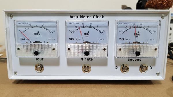
the 3 needle ammeters that make up the face of the clock

IC Clock Uses Ammeters For A Unique Time-Telling Display

It is a rite of passage for hackers to make a clock out of traditionally not-clock items. Whether it be blinking LEDs or servos to move the hands, we have all crafted our own ways of knowing when it currently is. [SIrawit] takes a new approach to this, by using ammeters to tell the time.

The clock is built using mostly CMOS ICs. A CD4060 generates the 1HZ clock signal, which is then passed to parallel counters to keep track of the hours, minutes, and seconds. [SIrawit] decided to keep the ammeters functioning as intended, rather than replacing the internals and just keeping the needle and face. To convert the digital signal to a varying current, he used a series of MOSFETs connected in parallel to the low side of the ammeters, with different sizes of current-limiting resistors. By sizing these resistors properly, precise movement of the needle could be achieved by turning on or off the MOSFETs. You can see the schematics and learn more about how this is achieved on the project’s GitHub page (at the time of writing, the most recent commits are in the ‘pcb’ branch).

In addition to the custom PCB that holds all the electronics, PCBs help make up the case as well. While the main body of the case is made out of a repurposed junction box, [SIrawit] had a PCB on an aluminum substrate manufactured for the front panel. While the board has no actual traces or electrical significance, this makes for a cheap and easy way to get a precisely cut piece of aluminum for your projects, with a sharp-looking white solder mask to boot.

We love to see cool and unique ways to tell the time, such as using Nixie Tubes to spell out the time in binary!

Continue reading “IC Clock Uses Ammeters For A Unique Time-Telling Display”

Relay Logic Nixie Tube Clock Checks All The Boxes

There are a few words in the electrical engineering lexicon that will perk any hardware hacker’s ears. The first of course is “Nixie tubes” with their warm cold war era ambiance and nostalgia inducing aura. A close second is “relay logic”. Between their place in computing and telecom history and the way a symphony of click and clatter can make a geek’s heart go pitter patter, most of us just love a good relay hack. And then there’s the classic hacker project: A unique timepiece to adorn our lair and remind us when we’ve been working on our project just a little too long, if such a thing even exists.

With those things in mind, you can forgive us if we swooned ever so slightly when [Jon Stanley]’s Relay Logic Nixie Tube Clock came to us via the Tip LineAdorned with its plethora of clicking relays and set aglow by four Nixie tubes, the Relay Logic Nixie Tube Clock checks all our boxes. 

[Jon] started the build with relay modules that mimic CD4000 series CMOS logic chips. When the prototype stage was complete, the circuit was recreated on a new board that mounts all 55 Omron relays on the same PCB. The result? A glorious Nixie tube clock that will strike envy into even the purest hacker’s heart. Make sure to watch the video after the break!

[Jon] has graciously documented the entire build and even makes various relay logic boards available for purchase if you’d like to embark on your own relay logic exploits . His site overflows with unique clock projects as well, so you can be sure we’ll be checking those out. 

If you feel inspired to build your own relay logic project, make sure you source genuine Omron relays, especially if your Relay Computer Masterpiece takes six years to build.

Thanks to [Daniel] for sending this our way. Got a cool project you’d like to share? Be sure to send it in via the Tip Line

Continue reading “Relay Logic Nixie Tube Clock Checks All The Boxes”