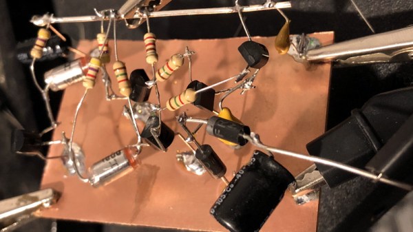
This summer, we saw the WHY (What Hackers Yearn) event happen in Netherlands, of course, with a badge to match. Many badges these days embrace the QWERTY computer aesthetic, which I’m personally genuinely happy about. This one used 18650 batteries for power, in a dual parallel cell configuration… Oh snap, that’s my favourite LiIon cell in my favourite configuration, too! Surely, nothing bad could happen?
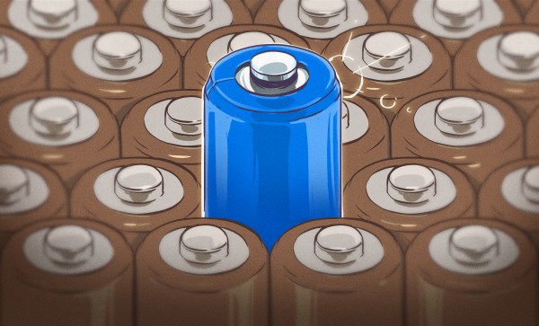
Whoops. That one almost caught me by surprise, I have to shamefully admit. I just genuinely love 18650 cells, in all glory they bring to hardware hacking, and my excitement must’ve blindsided me. They’re the closest possible entity to a “LiIon battery module”, surprisingly easy to find in most corners of this planet, cheap to acquire in large quantities, easy to interface to your projects, and packing a huge amount of power. It’s a perfect cell for many applications I and many other hackers hold dear.
Sadly, the 18650 cells were a bad choice for the WHY badge, for multiple reasons at once. If you’re considering building a 18650-based project, or even a product, let me show you what exactly made these cells a bad fit, and how you might be able to work around those limitations on your own journey. There’s plenty of technical factors, but I will tell you about the social factors, because these create the real dealbreaker here. Continue reading “Lithium-Ion Batteries: WHY They Demand Respect”