If you were to ask someone who works with RF a lot and isn’t lucky enough to do it for a commercial entity with deep pockets what their test instrument of desire would be, the chances are their response would mention a vector network analyser. A VNA is an instrument that measures the S-parameters of an RF circuit, that rather useful set of things to know whose maths in those lectures as an electronic engineering student are something of a painful memory for some of us.
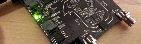
The reason your RF engineer respondent won’t have a VNA on their bench already will be fairly straightforward. VNAs are eye-wateringly expensive. Second-hand ones are in the multi-thousands, new ones can require the keys to Fort Knox. All this is no obstacle to [Henrik Forstén] though, he’s built himself a 30MHz to 6 GHz VNA on the cheap, with the astoundingly low budget of 200 Euros.
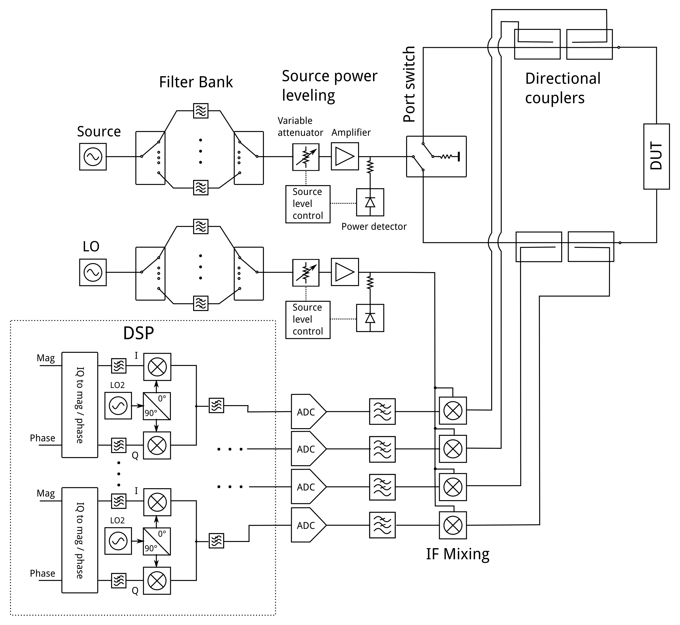
On paper, the operation of a VNA is surprisingly simple. RF at a known power level is passed through the device under test into a load, and the forward and reverse RF is sampled on both its input and output with a set of directional couplers. Each of the four couplers feeds what amounts to an SDR, and the resulting samples are processed by a computer. His write-up contains a full run-down of each section of the circuit, and is an interesting primer on the operation of a VNA,
[Henrik] admits that his VNA isn’t as accurate an instrument as its commercial cousins, but for his tiny budget the quality of his work is evident in that it is a functional VNA. He could have a batch of these assembled and he’d find a willing queue of buyers even after taking into account the work he’s put in with his pricing.
[Henrik]’s work has appeared on these pages several times before, and every time he has delivered something special. We’ve seen his radar systems, home-made horn antennas, and a very well-executed ARM single board computer. This guy is one to watch.
Thanks [theEngineer] for the tip.


