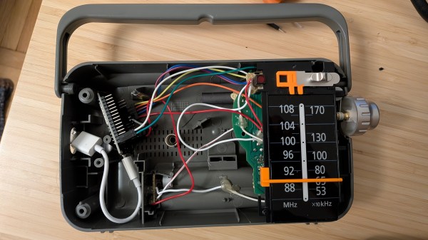
Humans of all ages like music, but you can’t exactly pass a toddler the aux cable. That’s not to say the younger set don’t have their own particular tastes– they absolutely do, and they absolutely love to take control and inflict them on the rest of us. [nbr23] has a toddler who loves both music and tactile controls, and decided to combine the two for them with a project he calls Radio-Gaga, which is a gutted Panasonic radio that calls up tunes via Home Assistant.
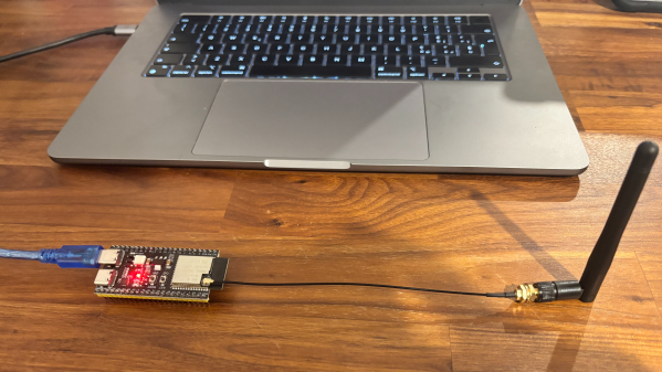
Interestingly enough the radio is now just a remote control– the speaker has been removed along with the rest of the radio hardware. The buttons and dials are still there, though, letting the toddler control what tunes are on offer and at what volume via couple of potentiometers hooked to an ESP32. The sound itself is being served up from the homelab to a USB speaker. There’s one notable flaw with this architecture: if the batteries die on the remote, “Let it Go” does not until an adult intervenes manually or recharges the remote.
One interesting lesson [nbr23] wanted to share was that he was able to improve an unsatisfactorily slow startup time by assigning the device a static IP on his network– apparently the single longest step in getting the tunes going was negotiating a DHCP lease. Skipping that gets the tunes playing in under a second, which is fast enough even for the most impatient of tiny humans.
If you prefer a more self-contained device, we’ve seen toddler jukeboxes that keep storage and speaker built-in, many with NFC control.