If you’ve been tearing electronic devices apart for long enough, you’ll know that the old gear had just as many mysteries within as the newer stuff. The parts back then were bigger, of course, but often just as inscrutable as the SMD parts that populate boards today. And the one part that always baffled us back in the days of transistor radios and personal cassette players was those little silver boxes with a hole in the top and the colorful plug with an inviting screwdriver slot.
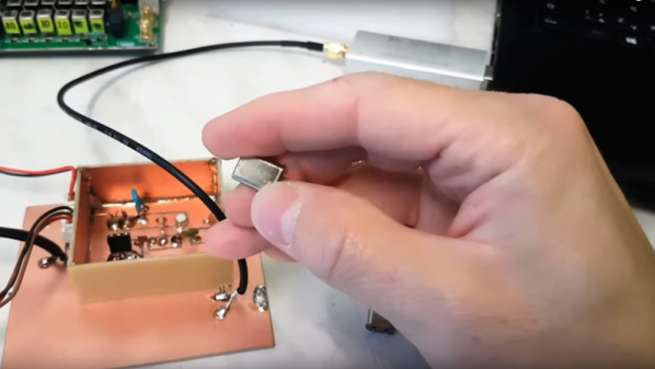
We’re talking about subminiature intermediate-frequency transformers, of course, and while we knew their purpose in general terms back then and never to fiddle with them, we never really bothered to look inside one. This teardown of various IF transformers by [Unrelated Activities] makes up somewhat for that shameful lack of curiosity. The video lacks narration, relying on captions to get the point across that these once-ubiquitous components were a pretty diverse lot despite their outward similarities. Most had a metal shell protecting a form around which one or more coils of fine magnet wire were wrapped. Some had tiny capacitors wired in parallel with one of the coils, too.
Perhaps the most obvious feature of these IF transformers was their tunability, thanks to a ferrite cup or slug around the central core and coils. The threaded slug allowed the inductance of the system to be changed with the turn of a screwdriver, preferably a plastic one. [Unrelated] demonstrates this with a NanoVNA using a nominal 10.7-MHz IFT, probably from an FM receiver. The transformer was tunable over a 4-MHz range.
Sure, IFTs like these are still made, and they’re not that hard to find if you know where to look. But they are certainly less common than they used to be, and seeing what’s under the hood scratches an itch we didn’t even realize we had.
Continue reading “A Look Under The Hood Of Intermediate Frequency Transformers”


