In the early 1980s when the 8-bit microcomputer boom was well under way, [Alan Faulds] was a student, and an owner of a Sinclair ZX81. He had ambitions to use it, in his words, “to control the world“, but since the Sinclair lacked an I/O port he was thwarted. He bought an expander board and a couple of I/O card PCBs from the British electronic supplier Maplin in the days when they were a mail order parts stockist rather than a chain of stores chasing Radio Shack’s vacated retail position.
Sadly for [Alan], he didn’t have the cash to buy all the parts to populate the boards, then the pressures of a final year at university intervened, and he never built those Maplin kits. They sat forgotten in their padded envelope for over three decades until a chance conversation with a friend reminded him of his unfinished student project. He sought it out, and set about recreating the board.
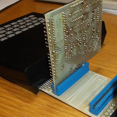 The ZX81 had a single port: a PCB edge connector at its rear that exposed all the Z80 processor’s lines. It was notorious for unreliability, as the tiniest vibration when a peripheral was connected would crash the machine. Maplin’s expansion system featured a backplane with a series of edge connector sockets, and cards with bare PCB edge connectors. Back in the 1980s it was easy to find edge connectors of the right size with the appropriate key installed, but not these days. [Alan] had to make one himself for his build.
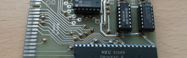
The I/O card with its 8255 and brace of 74 series chips was a double-sided affair with vias made through the use of little snap-off hand-soldered pins. [Alan] put his ICs in sockets, a sensible choice given that when he powered it up he found he’d put a couple of the 74 chips in the wrong positions. With that error rectified the board worked exactly as it should, giving the little ZX three I/O ports, albeit with one of them a buffered output.
We haven’t featured the little Sinclair micro as often as we should have here at Hackaday, it seems to have been overshadowed by its ZX Spectrum successor. We did show you a VGA ZX81 emulated on an mbed though, and a rather neat color video hack for its Brazilian cousin.