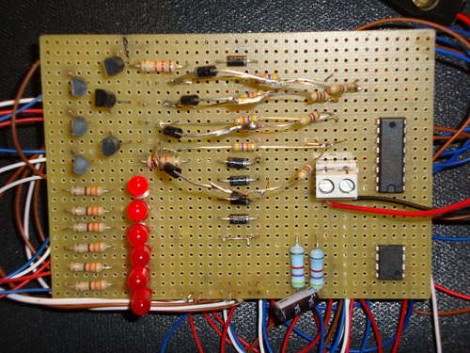
[Andrea] built this LED chaser using one logic chip. It illuminates all but one of the six LEDs, with the dim bit moving back and forth along the row in a chase sequence. This is something like an inverse Larson Scanner without the fading tail. But doing it with a logic chip instead of a microcontroller is a fun challenge.
Which brings us to the point of this feature. [Andrea] didn’t really post an explanation of how the circuit works. Usually missing details mean that we archive the tip and move on to the next one, but we think this provides a fun activity. Can you figure out how the circuit works? We already know that it’s using a CD4017 decade counter/divider chip. This gets its clock signal from a 555 timer circuit. [Andrea’s] schematic is a bit hard to read, but grab a copy, blow it up a bit (or use your browser zoom) and study the CD4017 datasheet (PDF) if you need to.
Want proof that it does actually work? It’s embedded after the break.
Continue reading “Challenge: Figure Out How This Logic-based Chaser Works”

