A few years ago, [Artem] learned about ways to focus sound in an issue of Popular Mechanics. If sound can be focused, he reasoned, it could be focused onto a plane of microphones. Get enough microphones, and you have a ‘sound camera’, with each microphone a single pixel.
Movies and TV shows about comic books are now the height of culture, so a device using an array of microphones to produce an image isn’t an interesting demonstration of FFT, signal processing, and high-speed electronic design. It’s a Daredevil camera, and it’s one of the greatest builds we’ve ever seen.
[Artem]’s build log isn’t a step-by-step process on how to make a sound camera. Instead, he went through the entire process of building this array of microphones, and like all amazing builds the first step never works. The first prototype was based on a flatbed scanner camera, simply a flatbed scanner in a lightproof box with a pinhole. The idea was, by scanning a microphone back and forth, using the pinhole as a ‘lens’, [Artem] could detect where a sound was coming from. He pulled out his scanner, a signal generator, and ran the experiment. It didn’t work. The box was not soundproof, the inner chamber should have been anechoic, and even if it worked, this camera would only be able to produce an image or two a minute.
The idea sat in the shelf of [Artem]’s mind for a while, and along the way he learned about FFT and how the gigantic Duga over the horizon radar actually worked. Math was the answer, and by using FFT to transform a microphones signals from up-and-down to buckets of frequency and intensity, he could build this camera.
That was the theory, anyway. Practicality has a way of getting in the way, and to build this gigantic sound camera he would need dozens of microphones, dozens of amplifiers, and a controller with enough analog pins, DACs, and processing power to make sense of all of this.
This complexity collapsed when [Artem] realized there was an off-the-shelf part that was a perfect microphone camera pixel. MEMS microphones, like the kind found in smartphones, take analog sound and turn it into a digital signal. Feed this into a fast enough microcontroller, and you can perform FFT on the signal and repeat the same process on the next pixel. This was the answer, and the only thing left to do was to build a board with an array of microphones.
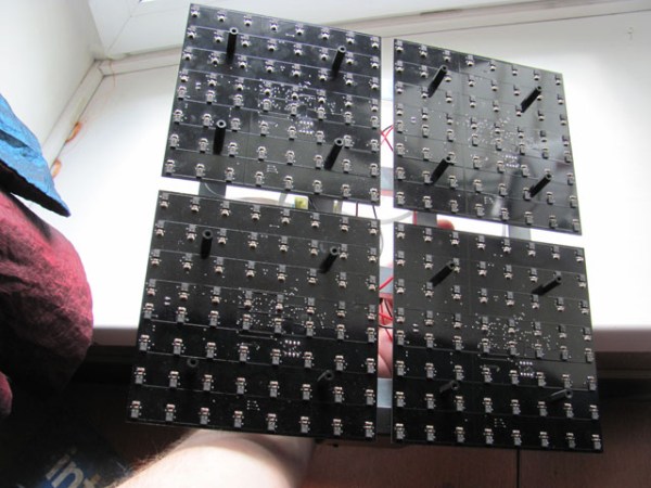
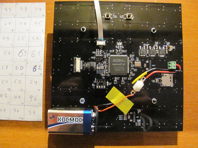
 [Artem]’s camera microphone is constructed out of several modules, each of them consisting of an 8×8 array of MEMS microphones, controlled via FPGA. These individual modules can be chained together, and the ‘big build’ is a 32×32 array. After a few problems with manufacturing, the board actually worked. He was recording 64 channels of audio from a single panel. Turning on the FFT visualization and pointing it at a speaker revealed that yes, he had indeed made a sound camera.
The result is a terribly crude movie with blobs of color, but that’s the reality of a camera that only has 32×32 resolution. Right now the sound camera works, the images are crude, and [Artem] has a few ideas of where to go next. A cheap PC is fast enough to record and process all the data, but now it’s an issue of bandwidth; 30 sounds per second is a total of 64 Mbps of data. That’s doable, but it would need another FPGA implementation.
Is this sonic vision? Yes, technically the board works. No, in that the project is stalled, and it’s expensive by any electronic hobbyist standards. Still, it’s one of the best to grace our front page.
[Thanks zakqwy for the tip!]


