When [Mahesh Venkitachalam] was experimenting with machine learning for audio applications on a Raspberry Pi, he found himself looking for a simple USB microphone. A cheap one was easy to find, but the sound quality and directionality left much to be desired. A large, studio-quality mic would be overkill, so [Mahesh] decided to simply build exactly what was needed: a compact, yet high-quality USB microphone that he called Mico.
The sensing device is a MEMS microphone that outputs a pulse density modulated (PDM) signal. There are chips available to directly interface such a microphone to a USB port, but [Mahesh] found them difficult to work with and therefore settled on something he knew already: the Raspberry Pi Pico platform. Luckily, someone had already figured out how to read out a microphone and present a USB device to a PC, so all that was needed was to put all the bits together into a convenient form factor.
The great thing about the Pico platform is that its main controller chip, the RP2040, is available as a separate component. [Mahesh] designed a sleek little PCB that holds the RP2040 along with the MEMS microphone and a USB connector. The end result looks tidy enough that it might have come out of a mass-produced gizmo. Those don’t usually come with full schematics and source code, but the Mico does: everything is available on its GitHub page for anyone to re-use and improve.
Those of us who have been working from home through video calls for the past year can attest to the rising demand for conferencing gear such as webcams and microphones. Not wanting to spring for a boring off-the-shelf solution, serial hacker [Andy Brown] decided to design his own USB solution from scratch and show us the process from start to finish.
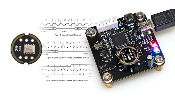
Deciding to go for a full digital design for the circuitry, the peripheral is based off of a MEMS microphone and an STM32 microcontroller doing the heavy lifting between it and a USB connection. [Andy] notes that MEMS microphones are very delicate and you have to design the PCB around the hole where the sound enters, which is why he went with a breakout board which has the component already soldered onto it.
As for the MCU, he reasons that since this is a off-one project which won’t be produced in large numbers, the 180 MHz ARM core shouldn’t be seen as overkill, since it also gives him more than plenty of headroom to do signal processing to make the sound clearer before sending it through to a computer by the USB audio device descriptor.
Once the components are chosen and the board designed, [Andy] goes into detail explaining the firmware he wrote for the STM32 to translate the PCM samples from the microphone’s I²S interface into a format better suited for the computer. He also describes how it then processes the audio, applying a graphic equalizer to reduce noise and then ST’s own Smart Volume Control filter, which works more like a compressor than a simple amplitude multiplication.
Finally, all files for the project, including board gerbers and the STM32 firmware are available at the bottom of his post, and to boot, a video demonstrating the project which you can check here after the break. [Andy]’s choice of microcontroller for this project is no surprise to us, given he’s already made his own development board for the STM32 G0 series. But if this digital microphone project is a bit too modern for you, why not try your hand at building a ribbon microphone instead?
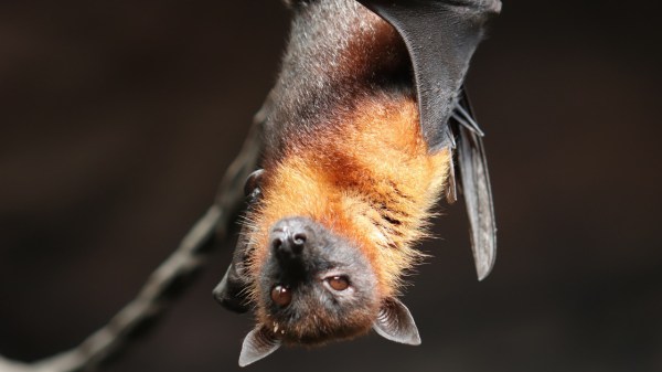
Bats are fascinating animals, and despite all the myth and creepiness surrounding them, they really remind one more of a drunk bird lost in the night sky than the blood-sucking creature they’re often made out to be. Of course, some really fall into that category, and unlike actual birds, bats don’t tend to grace us with their singsong — at least not in ways audible for us humans. But thanks to bat detectors, we can still pick up on it, and [Marcel] recently built a heterodyne bat detector himself.
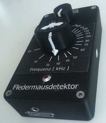
The bat detector (and an insight to the beauty of German language, where a bat is a flutter mouse)
The detector is made with a 555, an MCP6004 op amp, and a 4066 analog switch — along with a bunch of passives — and is neatly packed into a 3D-printed case with a potentiometer to set the volume and center frequency for the detection. The bat signal itself is picked up by a MEMS microphone with a frequency range [Marcel] found suitable for the task. His write-up also goes in all the mathematics details regarding heterodyning, and how each component plays into that. The resulting audio can be listened to through a headphone output, and after putting together an adapter, can also be recorded from his smartphone. A sample of how that sounds is added in his write-up, which you can also check out after the break.
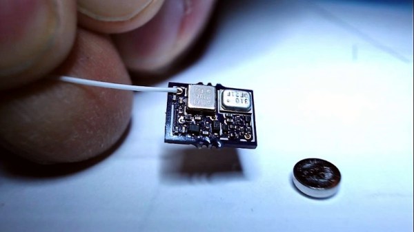
When it comes to surveillance, why let the government have all the fun? This tiny spy transmitter is just the thing you need to jumpstart your recreational espionage efforts.
We kid, of course — you’ll want to stay within the law of the land if you choose to build [TomTechTod]’s diminutive transmitter. Barely bigger than the 337 button cell that powers it, the scrap of PCB packs a fair number of surface mount components, most in 0201 packages. Even so, the transmitter is a simple design, with a two transistor audio stage amplifying the signal from the MEMS microphone and feeding an oscillator that uses a surface acoustic wave (SAW) resonator for stability. The bug is tuned for the 433-MHz low-power devices band, and from the video below, it appears to have decent range with the random wire antenna — maybe 50 meters. [TomTechTod] has all the build files posted, including Gerbers and a BOM with Digikey part numbers, so it should be easy to make one for your fieldcraft kit.
A few years ago, [Artem] learned about ways to focus sound in an issue of Popular Mechanics. If sound can be focused, he reasoned, it could be focused onto a plane of microphones. Get enough microphones, and you have a ‘sound camera’, with each microphone a single pixel.
Movies and TV shows about comic books are now the height of culture, so a device using an array of microphones to produce an image isn’t an interesting demonstration of FFT, signal processing, and high-speed electronic design. It’s a Daredevil camera, and it’s one of the greatest builds we’ve ever seen.
[Artem]’s build log isn’t a step-by-step process on how to make a sound camera. Instead, he went through the entire process of building this array of microphones, and like all amazing builds the first step never works. The first prototype was based on a flatbed scanner camera, simply a flatbed scanner in a lightproof box with a pinhole. The idea was, by scanning a microphone back and forth, using the pinhole as a ‘lens’, [Artem] could detect where a sound was coming from. He pulled out his scanner, a signal generator, and ran the experiment. It didn’t work. The box was not soundproof, the inner chamber should have been anechoic, and even if it worked, this camera would only be able to produce an image or two a minute.
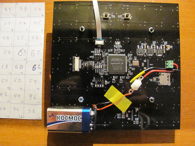
8×8 microphone array (mics on opposite side) connected to Altera FPGA at the center
The idea sat in the shelf of [Artem]’s mind for a while, and along the way he learned about FFT and how the gigantic Duga over the horizon radar actually worked. Math was the answer, and by using FFT to transform a microphones signals from up-and-down to buckets of frequency and intensity, he could build this camera.
That was the theory, anyway. Practicality has a way of getting in the way, and to build this gigantic sound camera he would need dozens of microphones, dozens of amplifiers, and a controller with enough analog pins, DACs, and processing power to make sense of all of this.
This complexity collapsed when [Artem] realized there was an off-the-shelf part that was a perfect microphone camera pixel. MEMS microphones, like the kind found in smartphones, take analog sound and turn it into a digital signal. Feed this into a fast enough microcontroller, and you can perform FFT on the signal and repeat the same process on the next pixel. This was the answer, and the only thing left to do was to build a board with an array of microphones.
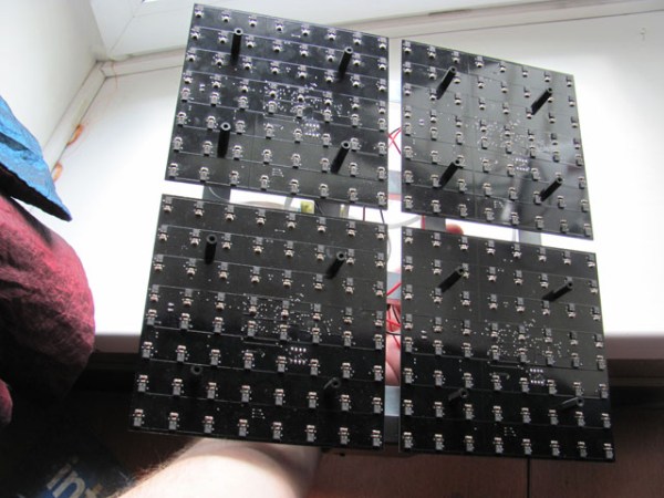
[Artem]’s camera microphone is constructed out of several modules, each of them consisting of an 8×8 array of MEMS microphones, controlled via FPGA. These individual modules can be chained together, and the ‘big build’ is a 32×32 array. After a few problems with manufacturing, the board actually worked. He was recording 64 channels of audio from a single panel. Turning on the FFT visualization and pointing it at a speaker revealed that yes, he had indeed made a sound camera.
The result is a terribly crude movie with blobs of color, but that’s the reality of a camera that only has 32×32 resolution. Right now the sound camera works, the images are crude, and [Artem] has a few ideas of where to go next. A cheap PC is fast enough to record and process all the data, but now it’s an issue of bandwidth; 30 sounds per second is a total of 64 Mbps of data. That’s doable, but it would need another FPGA implementation.
Is this sonic vision? Yes, technically the board works. No, in that the project is stalled, and it’s expensive by any electronic hobbyist standards. Still, it’s one of the best to grace our front page.

 [Artem]’s camera microphone is constructed out of several modules, each of them consisting of an 8×8 array of MEMS microphones, controlled via FPGA. These individual modules can be chained together, and the ‘big build’ is a 32×32 array. After a few problems with manufacturing, the board actually worked. He was recording 64 channels of audio from a single panel. Turning on the FFT visualization and pointing it at a speaker revealed that yes, he had indeed made a sound camera.


