Have JBC Soldering Handle, Will USB-C Power Deliver

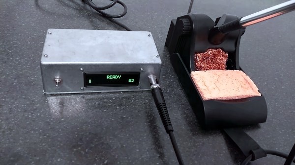
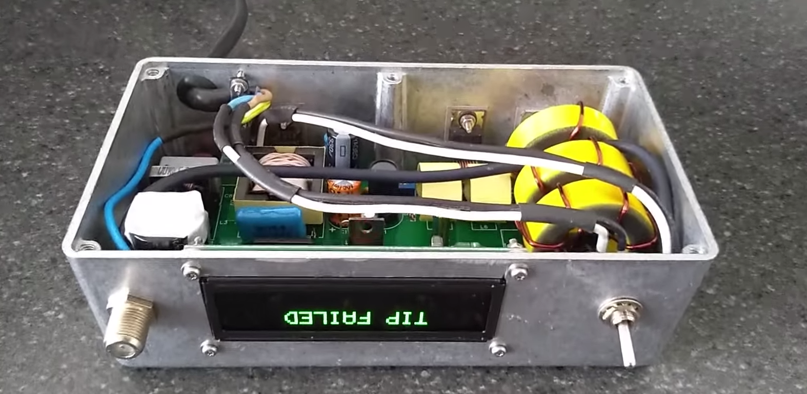
Frequent converter-of-tools-to-USB-C [Jana Marie Hemsing] is at it again, this time with a board to facilitate using USB Power Delivery to fuel JBC soldering iron handles. Last time we saw [Jana] work her USB-C magic was with the Otter-Iron, which brought Power Delivery to the trusty TS100 with a purpose built replacement PCBA. This time he’s taking a different approach by replacing the “station” of a conventional soldering station completely with one tiny board and one giant capacitor.

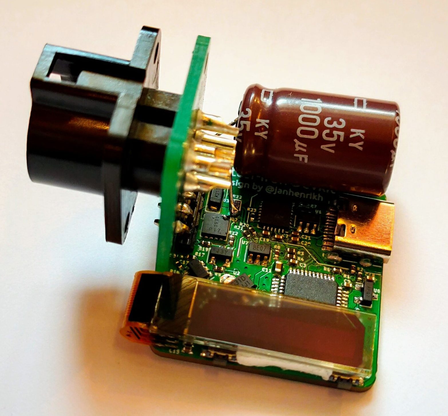
If you’ve been exposed to the “AC fire starter” grade of soldering iron the name JBC might be unfamiliar. They make tools most commonly found with Metcal’s and high end HAKKOs and Wellers on the benches of rework technicians and factory floors. Like any tool in this class each soldering station comes apart and each constituent piece (tips, handles, base stations, stands, etc) are available separately from the manufacturer and on the used market at often reasonable prices, which is where [Jana] comes in.

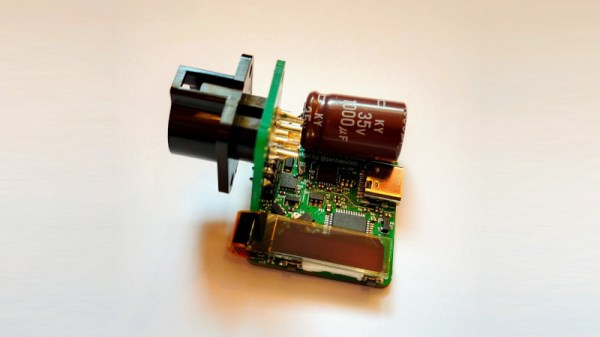
The Otter-Iron PRO is a diminutive PCBA which accepts a USB-C cable on one side and the connector from a standard JBC T245-A handle on the other. JBC uses a fairly typical thermistor embedded in the very end of the iron tip, which the Otter-Iron PRO senses to provide closed loop temperature control. [Jana] says it can reach its temperature setpoint from a cold start in 5 seconds, which roughly matches the performance of an original JBC base station! We’re especially excited because this doesn’t require any modification to the handle or station itself, making it a great option for JBC users with a need for mobility.

Want to make an Otter-Iron PRO of your own? Sources are at the link at the top. It sounds like v3 of the design is coming soon, which will include its own elegant PCB case. Check out the CAD render after the break. Still wondering how all this USB-PD stuff works? Check out [Jason Cerudolo’s] excellent walkthrough we wrote up last year.

Continue reading “Have JBC Soldering Handle, Will USB-C Power Deliver”

Homemade Magic Makes The Metcal Go

First soldering irons are often of the Radioshack or Maplin firestarter variety. They’re basically wall power shorted across a nichrome heater or similar with some inline resistance to make it harder to burn down the house. You plug them in, the current flows, and they get hot. Done.

If you stick with the hobby for a while, these eventually get replaced with something like the venerable HAKKO FX-888D or that one Weller everyone likes with the analog knob. These are much improved; having temperature control leads to a more consistently heated tip and much improved soldering experience.

Entering the electronics workplace one comes across the next level of quality soldering iron: high end HAKKOs, Metcals, JBCs, and the like. Using one of these irons is practically a religious experience; they heat in a flash and solder melts while you blink. They even turn off when you put the handpiece down! But they’re expensive to buy (hint: think used). What’s a hobbyist to do?

[SergeyMax] seems to have had this problem. He bit the bullet, figured out how the Metcal works, and made his own base. This is no mean feat as a Metcal might look like a regular iron but it’s significantly more complex than ye olde firestarter. The Metcal magic is based on a oscillating magnetic fields (notice the handpiece is connected via BNC?) interacting with a tip bearing a special coating. In the presence of the changing field the tip heats up until it hits its Curie temperature, at which point it stops interacting with the magnetic field and thus stops heating.

When the user solders, the tip cools by sinking its heat into the part and drops below the Curie temperature again, which starts the heating again. It’s like temperature control with the sensor placed absolutely as close to the part as possible and a nearly instant response time, without even a control loop! [SergeyMax] has a much more thorough description of how these irons work, which we definitely recommend reading.

So what’s the hack? Based on old schematics and some clever reverse engineering from photos [SergeyMax] built a new base station! The published schematic is as rich with capacitors and inductors as one could hope. He didn’t post source or fab files but we suspect the schematic and photos of the bare board combined with some tinkering are enough for the enterprising hacker to replicate.

The post contains a very thorough description of the reverse engineering process and related concerns in designing a cost efficient version of the RF circuitry. Hopefully this isn’t the last Metcal replacement build we see! Video “walkthrough” after the break.

Edit: I may have missed it, but eagle eyed commentor [Florian Maunier] noticed that [SergeyMax] posted the sources to this hack on GitHub!

Continue reading “Homemade Magic Makes The Metcal Go”