[Shahriar] of The Signal Path is back with another fascinating video teardown and analysis for your viewing pleasure. (Embedded below.) This time the target is an Agilent E5052A 7 GHz signal Source/Analyser which is an expensive piece of kit not many of us are fortunate enough to have on the bench. This particular unit is reported as faulty, with a signal power measurement that is completely off-the-rails wrong, which leads one to not trust anything the instrument reports.
After digging into the service manual of the related E5052B unit, [Shahriar] notes that the phase noise measurement part of the instrument is totally separate from the power measurement, only connected via some internal resistive power splitters, and this simplifies debugging a lot. But first, a short segue into that first measurement subsystem, because it’s really neat.

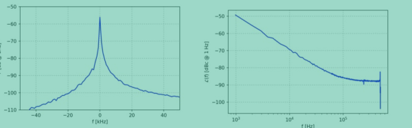
A traditional swept-mode instrument works by mixing the input signal with a locally-sourced low-noise oscillator, which when low-pass filtered, is fed into a power meter or digitizer. This simply put, down-converts the signal to something easy to measure. It then presents power or noise as a function of the local oscillator (LO) frequency, giving us the spectral view we require. All good, but this scheme has a big flaw. The noise of the LO is essentially added to that of the signal, producing a spectral noise floor below which signals cannot be resolved.
The E5052 instrument uses a cunning cross-correlation technique enabling it to measure phase noise levels below that of its own internal signal source. The instrument houses an Oven-Compensated Crystal Oscillator (OCXO) for high stability, in fact, two from two different vendors, one for each LO, and mounted perpendicular to each other. The technique splits the input signal in half with a power splitter, then feeds both halves into identical (apart from the LOs) down-converters, the outputs of which are fed into a DSP via a pair of ADCs. Having identical input signals, but different LOs (with different phase noise spectra) turns the two signals from a correlated pair to an uncorrelated pair, with the effects of chassis vibration and gravity effects also rolled in.
The DSP subtracts the uncorrelated signal from the correlated signal, therefore removing the effect of the individual LO’s effect on the phase noise spectrum. This clever technique results in a phase noise spectrum below that of the LOs themselves, and a good representation of the input signal being measured.
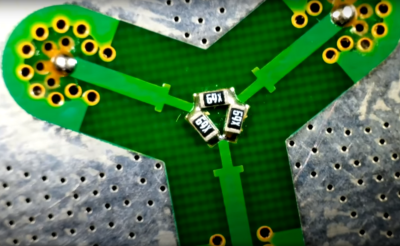
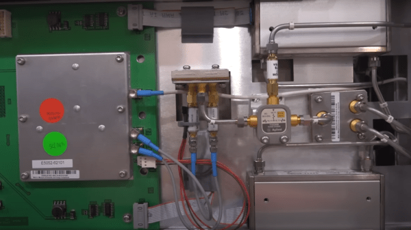
Handily for [Shahriar] this complex subsystem is totally separate from the dodgy power measurement. This second system is much simpler, being fed with another copy of the input signal, via the main resistive power splitter. This second feed is then split again with a custom power divider, which upon visual inspection of the input SMA connector was clearly defective. It should not wobble. The root cause of the issue was a cold solder joint of a single SMA footprint, which worked loose over time. A little reflow and reassembly and the unit was fit for recalibration, and back into service.
We’ve seen phase noise measurements a few times on these pages, like debugging this STM32 PLL issue.
Continue reading “A 7 GHz Signal Analyser Teardown And A Trivial Repair”