Everyone knows that you can never purchase enough projects off EBay, lest boredom might inadvertently strike. That’s why [Anthony Kouttron] got his mitts on an Agilent DSO-X 2014A digital oscilloscope that was being sold as defective and not booting, effectively just for parts. When [Anthony] received the unit, this turned out to be very much the case, with the front looking like it got dragged over the tarmac prior to having the stuffing beaten out of its knobs with a hammer. Fortunately, repairing the broken encoder and the plastic enclosure was easy enough, but the scope didn’t want to boot when powered on. How bad was the damage?
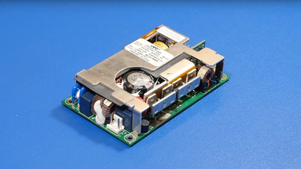
As [Anthony] describes in the article, issues with this range of Agilent DSOs are well-known, with for example the PSU liking to fry the primary side due to soft power button leaving it powered 24/7 with no cooling. The other is corrupted NAND storage, which he confirmed after figuring out the UART interface on the PCB with the ST SPEAr600 ARM-based SoC. Seeing the sad Flash block decompression error from the Windows CE said enough.
This led him down the rabbithole of finding the WinCE firmware images (nuked by Keysight, backed up on his site) for this scope, along with the InfiniiVision scope application. The former is loaded via the bootloader in binary YMODEM mode, followed by installing InfiniiVision via a USB stick. An alternate method is explained in the SPEAr600 datasheet, in the form of USB BootROM, which can also be reached via the bootloader with some effort.
As for the cause of the NAND corruption, it’s speculated that the scope writes to the same section of NAND Flash on boot, with the SPEAr600’s Flash controller documentation not mentioning wear leveling. Whether that’s true or not, at least it can be fixed with some effort even without replacing the NAND Flash IC.