Kapton Tape Aids In Drag Soldering Surface Mount Parts

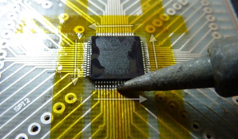
Drag soldering works exactly as its name implies, by dragging a bead of solder across fine-pitch pins you can quickly solder an entire row. The method relies on clean joints, so liquid solder flux is often used to make sure there is good flow. But if you’re drag soldering on boards that you’ve etched yourself the solder can sometimes run down the trace, rather than staying where you want it. Professionally manufactured boards don’t have this problem since they have solder mask covering the copper that doesn’t need soldering. [Ahmad Tabbouch] has a method that uses Kapton tape to act as a temporary solder mask on diy boards.

The process involves several steps. First, three strips are place horizontally across the board, leaving just a portion of the upper and lower pads exposed. Those pads are then tinned with solder, and a light touch with an X-acto knife is then used to score the tape covering the vertical rows of pads. Once the waste as been removed, two more strips are added and those rows are tinned. From there the chip is placed and soldered as we’ve seen before; first tacked in place, then fluxed, and finally drag soldered to complete the connections. This achieves a crisp and clean connection, presumably without the need to clean up your solder mess with solder wick.

Kapton tape resists heat, making it perfect for this process. We’ve also seen it used on hot beds for 3D printers, and as a smoothing surface for sliding mechanisms.

[via Dangerous Prototypes]

How To Populate A Surface Mount PCB

Reflow_08

Let’s face it friends, everything is moving toward surface mount components. We’ve seen quite a few features here that cover using stencils to populate boards and using ovens to reflow. [Oleg] has put together a tutorial on the process he uses to populate and reflow his own boards.

[Oleg] is the creator of the USB Isolator and therefore has a need to frequently populate the same board. He’s using an acrylic frame that fits the PCB perfectly to hold it in place so that paste and be applied right up to the edges of the board. He ordered a laser cut Kapton stencil for applying the solder. The paste is squeegeed into the stencil holes, the stencil is removed, and parts are placed with tweezers and a steady hand. For the final step, the boards go into an old toaster oven for reflow.

[Oleg] uses temperature marker on his boards to monitor the progress of the reflow. This marker is basically a crayon that begins to melt at a specific temperature. When the board has cooled, the melted mark can be scraped away or removed with alcohol.

Of course this is only really useful if you have a bunch of high-quality boards to populate. But with the relatively low cost of getting professionally made boards we think the need for this type of assembly process is on the rise.

Parts: 0.1uF Decoupling Capacitors

Most ICs need to be decoupled from their power supply, usually with a 0.1uF capacitor between each power pin and ground. Decoupling is usually used to remove noise and to smooth power fluctuations. Every project will need a few decoupling capacitors; our mini web server project has three ICs that require a total of 11. This can be an expensive part to buy in singles, so it’s crucial to stock up online. Read more about our favorite bulk through-hole and surface mount decoupling capacitors after the break. Continue reading “Parts: 0.1uF Decoupling Capacitors”