Wanting to control a split flap display that was not near a computer [Tom] looked to a common solution for communicating over distances not practical for I2C or SPI. He developed his own hardware and packet format using the RS-485 protocol.
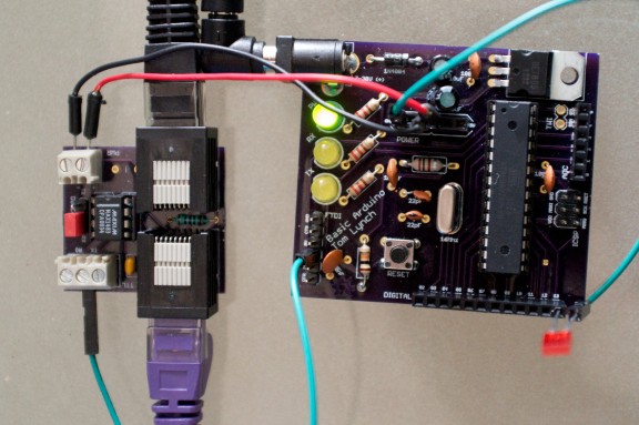
This is part of a larger project he has been working on to feed data to a split flap display that he plans to hang on the wall. RS-485 is designed to work over long distances and overcome noise issues. The core of the communications system is the board seen on the left. It uses a MAX1483 chip, a pair of RJ45 jacks for Ethernet cables, and two terminal blocks for power and communications. There are a few nice things about this. The board acts as a pass-through making it easy to chain nodes together, and the data structure is completely independent of the hardware itself. Because of this [Tom] developed his own packet format that will be a bit more resilient than the Arduino networking scheme we looked at the other day.


Any time I have a need for a simple protocol like this I use S.N.A.P.
http://www.hth.com/snap/
I’ve used it a lot and it has always served me well. I found it years ago.
–
S.N.A.P is an free and open network protocol.
– Easy to learn, use and implement.
– Free and open network protocol.
– Free development tools available.
– Scaleable binary protocol with small overhead.
– Requires minimal MCU resources to implement.
– Up to 16.7 million node addresses.
– Up to 24 protocol specific flags.
– Optional ACK/NAK request.
– Optional command mode.
– 8 different error detecting methods (Checksum, CRC, FEC etc.).
– Can be used in master/slave and/or peer-to-peer.
Oh Snap!
How is this or SNAP better than TCP/IP?
RS485 can work over a distance of 1200 metres (4000 feet). Ethernet is what? 100m?
Much simpler.
Do people do TCP/IP over RS485? I’ve never heard of that.
I believe that would be SLIP (serial line internet protocol).
I’ve seen SLIP over RS232. I suppose that SLIP over RS485 is reasonable. PPP, too.
I’ve used IP over RS232 before using SLIP and PPP; works good at RS232 speeds. Use PPP.
http://www.synapse-wireless.com/documents/products/SYNAPSE_SNAP.pdf
or
http://en.wikipedia.org/wiki/Subnetwork_Access_Protocol
Sorry it would be nice to clarify, I will be honest in saying that much of this is above me (my protocol does not process protocols).
I did clarify by pointing to this link: http://www.hth.com/snap/
The S.N.A.P. that I was referring to is neither of the protocols that you linked to.
That’s a nice, compact design. I like it. Props for designing his own framing. Adding POE would make this really awesome.
Why? RS485 isn’t ethernet, even if the connectors look similar.
POE exploits the fact that 10×100 baseT internet only uses 2 pairs.(out of 4).. so you can run power over the unused wires.
RS485 is a 3 wire serial link. 8 wires – 3 wires = 5 wires not doing anything….so why not run power on them.
POE is Power Over Ethernet. You would be adding Power to something that is Ethernet to get POE.
You just mean run power? In this case there are 8 wires, but there is no cable definition for RS485.
You could still follow the POE standard even if the data lines were not technically Ethernet. You could also obviously understood what I meant, so why be a semantic douche?
Matt: I don’t use childish name calling, so if you want that from me you’l be disappointed. POE is more than “run power on wires” and the reason for my comment is that enough people are perceiving this hack as somehow related to Ethernet.
You, I’m sure, will insist on using the term POE incorrectly. That is your choice.
That’s funny…I saw no confused statements about this being TCP/IP. The only confusing statements I see are the snarky “It’s not TECHNICALLY Ethernet” comments.
Power over ethernet doesn’t use unused pairs, because gigabit uses all 4 pairs. It adds a dc bias to one of the pairs. You should check out the wikipedia article.
485 uses http://en.wikipedia.org/wiki/Differential_signaling so in full duplex it uses 5 (or more)
If designed properly and the nodes do not have significant power requirements (usually a design issue), one can phantom power the nodes, ie use the power on the rx line(s).
There is no reason it couldn’t have a 5v power line but I wonder how the length cable runs might cause the power to drop off down the line, and also if there might be noise issues? Regardless for my needs each node will have a motor needing a fair chunk of power so it isn’t appropriate for the project, I have thrown it up on GitHub so you could always add it.
If you want to send power through cat5 cable you will have to step up the voltage so that you minimize losses, and then step it down at the destination. The amount of power transferable is still rather limited.Sending 5V directly is not an option unless your calbe is short and you draw little current.
Thanks for that, as I say, not important for my needs but if someone wants to hack my project under CC licence then sure!
Eagle says those files are “This is not an EAGLE file.”
Have you downloaded the newest EAGLE with it’s XML feature, it was made using 6.2.0?
Works fine when I open it here.
I guess whenever I see RS-485, I immediately jump to Modbus. Tons of equipment speak it, open and typical for just about any control guy. I see they have a Modbus library for Arduino: http://www.arduino.cc/playground/Code/ModbusMaster
Here too, for me 485=modbus! . And of course a lot of “free scada” floating around so no need to write PC apps!
This is a very nice setup and designed well. I also believe adding POE in the future would even add to the beauty of this design.
Power Over Ethernet? This isn’t Ethernet.
Just run power and ground wires along with the two differential communication wires.
or bundle them all into a single cable with a simple rj45 connector and have be able to connect signal and power to a module with one ‘click’.
The nice thing about standards are there are so many of them to pick from.
That is an 8p8c modular connector not RJ45.
Very nice indeed! i dig your minimal Arduino board too!
Hmm, what’s the difference between the MAX1482 and the MAX485 (or TI’s equivalent: SN75176B)? Is it only that the former is full duplex? If so, then what’s the difference between the 1483 and the 485?
This is what datasheets are for. If you had read it, the main difference is the 1482 has a 20uA operating current with a guaranteed 256node limit.
The MAX1482 and indeed most of those RS-485 line driver chips from a number of manufacturers are pin for pin compatible but this one has 1/8th load meaning you can have 256 devices in theory on the same bus.
The 75176 is older, made with bipolar transistors, consumes more power and it is about 6-7 times cheaper than the MAX1483 and about 4 times cheaper than the classic MAX485. (from where i buy my components).
Aye, but it very much depends on what your needs are, the MAX485 doesn’t offer 1/8th load, thus why it wasn’t used.
I wonder why there’s so much confusion happening between what RS485 and ethernet is…
because the average (uneducated) thinks ethernet is defined by the wire and connectors. this hack uses rj45 connectors and twisted pair. the uneducated thinks this is ethernet when in fact, it is just the wiring he chose.
The POE standard says nothing about the data connections. It just specifies how to run power through “Ethernet Cable”…you could just run power over twisted pair and have it considered POE. So it is not unreasonable to call it POE, since from the power point of view, that is what it would be. The fact that it is not Ethernet on the data side is regardless.
In fact he is using http://en.wikipedia.org/wiki/8P8C#8P8C
I made the mistake of thinking it was Ethernet by looking at the picture and not actually reading the title RS485 or the article. Only skimmed it. I was also doing 6 different things at once but I should of known better as I created a implementation using the RS485 standard not to long ago. In other words I fail at doing several things at once and just skimming.
Probably because there are “Ethernet connectors” in the picture. And I say that quoted phrase tongue-in-cheek.
This reminds me of an older gentleman that couldn’t send emails on his computer. The problem? The “email cable” fell out the back. Once he reattached the “email cable” then he could send emails again.
People see the cable as an Ethernet cable and not as an RS485 connection. Hence adding power is POE despite the fact that there is no Ethernet going on here. The communication would be TCP/IP, despite the fact that it is not Ethernet.
When all you have is a hammer, everything looks like a nail.
Couldn’t find the schematics for the RS485 board so can’t be sure but I didn’t see any termination. RS485 needs termination at each end, typical 120 ohm or so.
In a multidrop configuration with duplex communication you also need pull up and pull down resistors to put the bus in a known state when there is no communication since there is no driver that is active. Failure to do this will result in lot of communication errors in a noisy environment.
There are 4 pairs of wire in a CAT6 cable so one or two pairs could carry power to each device if the current consumption is low. Preferably higher voltage like 24V since there will be some voltage drop. With switching voltage regulators on each node it’s no problem to get 5V or 3.3V without having to use a heatsink.
“multidrop configuration with duplex communication” should have been “multidrop configuration with HALV duplex communication” meaning only one master at a time.
If there a several nodes that could initiate communication at any time you need some type of collision detect. Easiest way is to read from the bus at the same time as you send. If you don’t receive what you send wait a random time and then transmit again.
IME the hardware with a RS485 bus is the easy part.It’s the software with error detection, retransmittion, timeouts etc that is the tricky part. At least when you put it in industrial environments.
Ethernet is only 100m betwean nodes but you would just run some fiber when you need anything longer. I tink singlemode 1000base LX goes to 10 km or so.
In reality, since he is using cat5 cable, he could implement RS422 instead, which would allow for full duplex and reduce collisions. The max148x family of chips even support 422 already, so it would only take a board revision (or some jumper wires) to change it.
The 100m Ethernet limit is a function of the ethernet protocol + media (cat5(e), cat6). You can comfortably get 1000m+ over 485, in a noisy environment, provided you are willing to compromise on baud rate – it was designed specifically for this purpose, which is why it uses differential signalling.
I have uploaded it to GitHub:
https://github.com/unknowndomain/Basic-Arduino
https://github.com/unknowndomain/RS-485-Adapter
I did a lot of reading about RS-422 and RS-485 and it turns out that you don’t always need a terminating resistor and as a result you shouldn’t use one by default but when actually needed as it can be bad. Additionally the use of a 120 ohm resistor isn’t always true either, it depends on the cable you use, CAT5 isn’t 120 ohm, it’s 100 ohm (if I recall correctly).
RS-422 wouldn’t be suitable in this environment as it is intended to be used to extend RS-232 lines on a point-to-point basis, where as RS-485 is intended for multi-node communication, in my case I am using multi-drop but you could use the MAX1482 which has a separate line driver and line receiver allowing full duplex, however you’d need to figure out how to avoid collisions, using a variety of techniques.
RS-485 is essentially what DMX uses and the DMX architecture was what I wanted to mirror, multiple fixtures in a ‘universe’ that listen, with one device barking orders out but not getting a response, only presuming that the fixtures heard the message. Using my simple protocol/messaging frame I haven’t had any messages interpreted incorrectly over 50 meters of CAT5.
Additionally implementing the MCPM mode of the ATMega reduces the data nodes have to listen to. This can easily be found in the datasheet. In short – there is a 9 bit mode of the UART – the 9th bit means that the following byte is an address. Every packet ends with the address again. If a node sees it’s address it starts building a packet and if a timeout is not reached and the CRC is OK then the packet can be used further.
I am using MCPM with SNAP like protocol and it works well.
Dear Hack a day writers: please learn what a protocol is. RS 485 is not a protocol, it is a standard for a physical interface.
Protocol is a set of rules regarding how information is exchanged. The same protocol can be used with different physical interfaces.
+1
Add it to the list but don’t hold your breath ;)
Funny all the confusion over CAT5/6 cable and RJ45 connectors being used for something other than Ethernet. They’re a convenient choice whenever a robust multi-conductor cable and connector is needed. I’ve used them for carrying audio, video, I2C, SPI, power, and more.
Simply want to say your article is as astounding. The clarity for your put
up is just cool and i could assume you are a professional on this subject.
Fine together with your permission let me to grab your RSS feed to
keep up to date with forthcoming post. Thank you one million and please continue the enjoyable work.