[Pyrow] wanted to upgrade his garage door opener remote. It worked just fine, but changing those tiny batteries out can be an inconvenience. Plus, the remote control was taking up valuable storage space and would always rattle around while driving. [Pyrow] decided to make use of an Omron E2K-F10MC2 capacitive touch sensor to fix these issues.
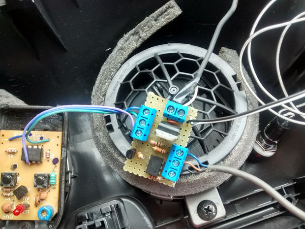
[Pyrow’s] circuit still makes use of the original remote control. He just added some of his own components to get it to do what he wanted. The circuit is powered by the car’s battery, so it never needs a battery replacement. The circuit is protected with a fuse and the power is regulated to prevent electrical spikes from burning up the original remote control. The actual circuit is pretty simple and uses mostly discrete components. It’s all soldered onto proto board to keep it together. He only had to solder to three places on the original remote control in order to provide power and simulate a button press.
Next, [Pyrow] took his dash apart. He used double-sided tape to attach the touch sensor to the back of the dash. After securing the electronics in place with tape, he now has a working hidden garage door opener. Full schematics are available in the writeup linked above. Also, be sure to watch the demonstration video below.


Batteries in remote controls last how long? Years? How long does it take to change them out? 5 minutes, tops? How long did it take to prototype this up and install it? How many times could they have simply changed the batteries in the time it took them to conceive, design, source, build and test this particular upgrade? I am not trying to be *too* cynical here because it’s actually a neat hack and capacitive sensors are just cool but the realist in me wonders was it actually worth it? I can’t answer that for the builder.
Hackers don’t do things because is worth it or they need it, they do it just because they can.
Agreed, but only to a point. I see value in learning new things, applying new things. Testing new ideas. Maybe I just tend towards trying to solve problems by building new things when I can use said resultant *thing* to produce other things or somehow become more than just the sum of its parts or just another kludgly solution. It’s refreshing when somebody else has already solved the issue but as so many of us have come to learn, that’s rarely the case for the kind of solutions we seek. I guess I am just lamenting the amount of time it takes to actually put things like this together. Should there not be an easier way? Is there?
I don’t think he did it because it’s easier. He did it because it’s a fun project, and now when he wants to open the garage door he can feel proud that he has a slick way to do it.
http://xkcd.com/1205/
Excellent illustration.
You’re missing the point entirely I think. You wouldn’t do this just to save the seconds it would take to replace the battery.
If you pull up to your house and have to fish out the remote to open the door its a pain in the ass. Having it integrated into a permanent position on the dash is much more convenient.
The CR2032 cells in those remotes also drop a lot of voltage when transmitting (like 2V down from 3V when transmitting). If you have it mounted in the dash you can use a better power source and easily double the transmit range
in the same line from what Afliw said, it’s a hobby, we do this because we enjoy.
And it really helps a lot, the most annoying thing is finding your remote when you are in a hurry (It’s very rare to lose it but when it happens it’s 100% chance you get mad). And there are a lot more positive points on it.
I have an RF-remote for a gate at my workplace, it uses 2 CR2032s and those have to be replaced every couple of months, otherwise the range gets really short. Same goes for the central lock remote for my car. Meaning, so far I haven’t see one that would last for years.
And don’t forget to complain aboot all the starving children in japan he could have fed with the plastic from the remote… Or something…
Looks a lot like a gate, not a garage door.
Beware of the highly polished spot on the dash or at least dust free spot.
You know what would be fun…
Use your car to wirelessly power your garage door… Sounds fun right?
i don’t really understand how the optocoupler is used in the schematic. Can anyone explain?
The problem at the schematics is when you don’t know much about analog electronics and you don’t have the best components at the time
I made this circuit at the weekend and didn’t have any other option close by.
The sensor that I bought at ebay has NPN and NC at output, used the 4N25 like an relay to switch off when the sensor is activate.
It worked correctly and I used it for like a year with no problems :)
Now I did another version using an CMOS 4011 that can be used for NPN/PNP and NC/NO sensors.
I think I have it – the whole system is powered at 12V by an LM7812. The sensor signal output is a negative sink output – which likely can’t accept much current or voltage, but can run the led in an optocoupler just fine. The final input to the factory remote is a 12V positive signal provided by the discrete transistor, but that transistor needs a positive base signal to activate. So our weak negative signal from the sensor is enough to drive the optocoupler, which is strong enough to operate the discrete transistor, which is rated for 30v and has no problem providing 12v to the factory remote. I’m guessing the current draw from the remote when triggered is too much for the optocoupler to source, thus the need for the transistor.
My diagram-fu is weak. See above explanation from Henrique and ignore my babbling.
I don’t understand the negative comments—this is a great little hack.
It works and he didn’t use a microcontroller – so kudos for a nice hack.
This will never work reliably unless the engine is started. A LM7812 Vreg have a dropout voltage of around 2 volts, so unless you have a supply of 14V in, your voltage out will not be stable. Better go for a 7810, since it can relibably regulate at all times. Also 10V is fine for the operation of the transmitter.
Kids, learn your Vreg-basics :)
What do you think ? That he open the door from the car, then goes down and push it through by hand ?
Seriously, why do you use a remote gate opener for when inside your car if not to drive it through said gate…
Is that a Pontiac?
Its a Nissan March
Didn’t the make a compound charged version or are they all built that way? Wish i could find one here in the US.
this is a good way to upgrade your garage door opener. this is really a innovative idea and this work will keep you busy.
Beware of the highly polished spot on the dash or at least dust free spot.