[Sam Miller], [Sahil Gupta], and [Mashrur Mohiuddin] worked together on a very fast LED matrix display for their final project in ECE 5760 at Cornell University.
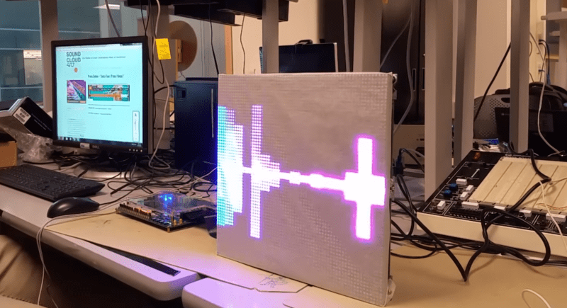
They started, as any good engineering students, by finding a way to make their lives easier. [Sam] had built a 32×32 LED matrix for another class. So, they made three more and ended up with a larger and more impressive 64×64 LED display.
They claim their motivation was the love of music, but we have a suspicion that the true reason was the love all EEs share for unnaturally bright LEDs; just look at any appliance at night and try not be blinded.
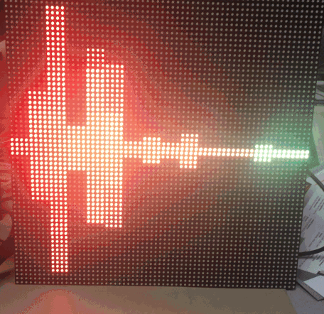
The brains of the display is an Altera DE2-115 FPGA board. The code is all pure Verilog. The FFT and LED control are implemented in hardware on the FPGA; none of that Altera core stuff. To generate images and patterns they wrote a series of python scripts. But for us it’s the particle test shown in the video below that really turns our head. This system is capable of tracking and reacting to a lot of different elements on the fly why scanning the display at about 310 FPS. They have tested display scanning at twice that speed but some screen-wrap artifacts need to be worked out before that’s ready for prime time.
The team has promised to upload all the code to GitHub, but it will likely be a while before the success hangover blows over and they can approach the project again. You can view a video interview and samples of the visualizations in the videos after the break.
Thanks to their Professor, [Bruce Land], for submitting the tip! His students are always doing cool things. You can even watch some of his excellent courses online if you like: Here’s one on the AVR micro-controller.


Looks amazing! Huge kudos to the guys who made it.
Now the tough business question. Is there a use case here for an FPGA when I could just use a PC or SBC to drive this LED array? I realize a controller for the LED array would still be required, but surely USB has enough bandwidth to drive a 12-bit, 4096 pixel display at 300Hz.
12bit*3colors*4096pix*300hz = 5400kbit/s, so usb2.0 is required just for sending pixel data. And the controller is STILL required, probably in fpga. Why not just use fpga? Especially when you are making project for fpga course.
That should be 5400 Kbyte/s, not bits.
12bit*3colors*4096pix*300hz = 44236800 bit/s
44236800/8/1024 = 5400 KByte/s
Additionally, USB 2.0 has no guaranteed latency spec, and throughput is dependent on how many devices are connected to your root hub. I wouldn’t dare try to stream realtime data, so local storage and an FPGA or micro would be preferred.
Yep, it should be kbytes, my bad, sorry.
The speed is very impressive indeed
In the link it says they are driving the FPGA pins at 20-40mhz, which gives them 310-620fps. 40mhz caused some artifacts, and 2mhz (30fps) caused flickering scan line. Also note its 4 separate displays actually. All that while processing 48khz audio to detect rhythm patterns. So yeah an SBC probably wouldn’t cut it, at least not for this level of responsiveness. Oh yeah, and they did it all in 5 weeks! Great hack, these guys have a promising future
But Why?
I get it — learn FPGA programming, how to wire up a commercial LED panel, power supply considerations, etc.
Great student project. And there’s the undeniable attraction to bright shiny things.
But what’s the purpose of a low-resolution, expensive, inflexible display like this? You can make a much more capable visualizer with a PC and and a standard LCD, and probably quicker and cheaper too. Want it to look like a low-resolution array of LEDs? Just program it that way.
It’s almost certainly cheaper and easier to use an LCD for anything more than around a 16×16 array. So, why the attraction to arrays of discrete LEDs?
This is hackaday no need for whys… ‘Just for the lulz’
Impressive stuff by the way.
LEDs are brighter than any LCD. Also you get true black. Want a bigger display? Just replace each LED with array of LEDs. And don’t forget the cool factor. FPGAs are better at parallel processing and this project would require that. With FPGA you get a Verilog code that can be turned into ASIC if you wish to mass-produce the thing. SBC would add lots of overhead to the whole thing. It must boot up, load an OS from SD card, run the script to process audio data and drive the display. And I doubt it can achieve this speed, especially with LCDs that are not as fast as LED matrices.
What else could you do with a FPGA that would be that cool and educational at the same time?
you may for example visit shanghai train station (or a similar location for that matter) to get the visual first-hand answer to “why”, “what” & “cheaper for anything more than 16×16”.
http://welcometochina.com.au/wp-content/uploads/2010/05/shanghai-train-station.jpg
Brightness. An LED array looks much better as a mounted fixture than an LCD can.
It would be nice to see a visualisation style that was as meaningful as this,
https://www.youtube.com/watch?v=PUq6prgr2lI
And the same piece done in a slightly more symbolic way that would probably tax the smaller FPGAs as it would need (for real-time) some form of timbral feature extraction, but it is doable.
https://www.youtube.com/watch?v=cZ7tZFigmac
A while ago I saw a shirt someone had made with neopixels. The shirt detected bluetooth devices and lit up whenever someone with a phone walked by. I really want to mix something like that with something like this. Then wear it and dj some music.