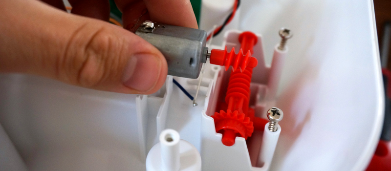
We’ve all taken apart a small toy and pulled out one of those little can motors. “With this! I can do anything!” we proclaim as we hold it aloft. Ten minutes later, after we’ve made it spin a few times, it goes into the drawer never to be seen again.

It always seems like they are in everything but getting them to function usefully in a project is a fool’s errand. What the heck are they for? Where do people learn the black magic needed to make them function? It’s easy enough to pull out the specification sheet for them. Most of them are made by or are made to imitate motors from the Mabuchi Motor Corporation of Japan. That company alone is responsible for over 1.5 billion tiny motors a year.
More than Just the Specs
In the specs, you’ll find things like running speed, voltage, stall current, and stall torque. But they offer anything but a convincing application guide, or a basic set of assumptions an engineer should make before using one. This is by no means a complete list, and a skip over the electrics nearly completely as that aspect of DC motors in unreasonably well documented.

The first thing to note is that they really aren’t meant to drive anything directly. They are meant to be isolated from the actual driving by a gear train. This is for a lot of reasons. The first is that they typically spin very fast, 6,000 – 15,000 rpm is not atypical for even the tiniest motor. So even though the datasheet may throw out something impressive like it being a 3 watt motor, it’s not exactly true. Rather, it’s 3 N*m/s per 15,000 rotations per minute motor. Or a mere 1.2 milliwatt per rotation, which is an odd sort of unit that I’m just using for demonstration, but it gives you the feeling that there’s not a ton of “oomph” available. However, if you start to combine lots of rotations together using a gear train, you can start to get some real power out of it, even with the friction losses.
The only consumer items I can think of that regularly break this rule are very cheap children’s toys, which aren’t designed to last long anyway, and those powered erasers and coffee stirrers. Both of these are taking for granted that their torque needs are low and their speed needs are high, or that the motor burning out is no real loss for the world (at least in the short term).
This is because the motors derate nearly instantly. Most of these motors are hundreds of loops of very thin enameled wire wrapped around some silicon steel plates spot welded or otherwise coerced together. This means that even a small heat event of a few milliseconds could be enough to burn through the 10 micrometer thick coating insulating the coils from each other. Practically speaking, if you stall a little motor a few times in a row you might as well throw it away, because there’s no guessing what its actual performance rating is anymore. Likewise, consistently difficult start-ups, over voltage, over current, and other abuse can quickly ruin the motor. Because the energy it produces is meant to spread over lots of rotations, the motor is simply not designed (nor could it be reasonably built) to produce it all in one dramatic push.
Making Contact
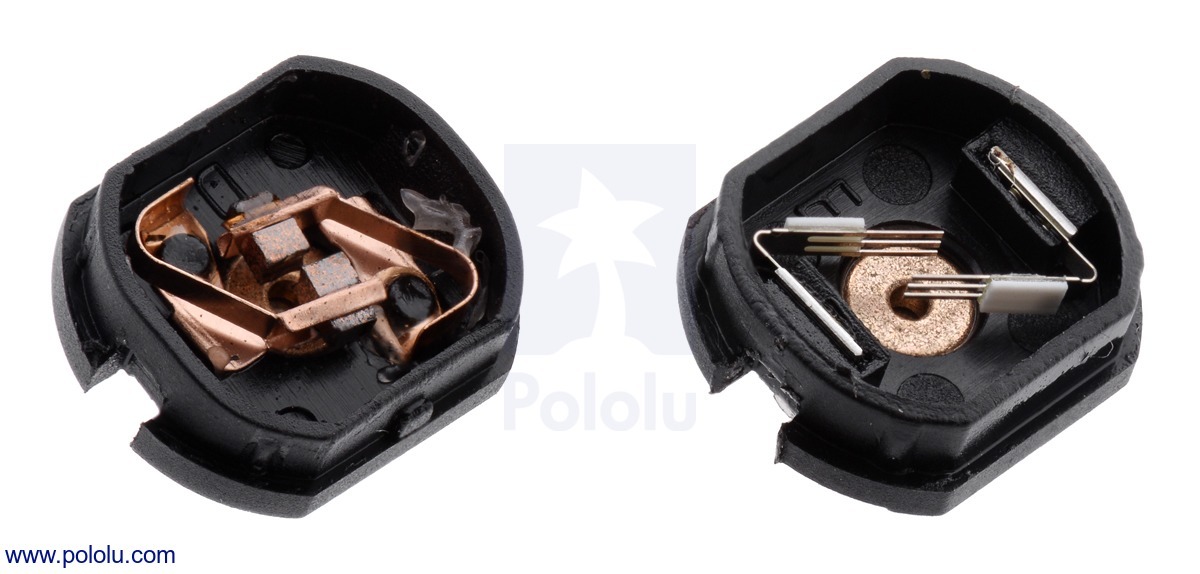
This brings me to another small note about these tiny motors. Most of them don’t have the carbon brushes one begins to expect from the more powerful motors. Mostly they have a strip of copper that’s been stamped to have a few fingers pressing against the commutator. There’s lots of pros to these metal contacts and it’s not all cost cutting, but unless you have managed to read “Electrical Contacts” by Ragnar Holm and actually understood it, they’re hard to explain. There’s all sorts of magic. For example, just forming the right kind of oxide film on the surface of the commutator is a battle all on its own.
It’s a weird trade off. You can make the motor cheaper with the metal contacts, for one. Metal contacts also have much lower friction than carbon or graphite brushes. They’re quieter, and they also transfer less current, which may seem like a bad thing, but if you have a stalled motor with hairlike strands transferring the pixies around the last thing you’d want to do is transfer as much current as possible through them. However, a paper thin sheet of copper is not going to last very long either.
So it comes down to this, at least as I understand it: if bursts of very fast, low energy, high efficiency motion is all that’s required of the motor over its operational life then the metal strip brushes are perfect. If you need to run the motor for a long stretches at a time and noise isn’t an issue then the carbon brush version will work, just don’t stall it. It will cost a little bit more.
Take Care of Your Tiny Motors
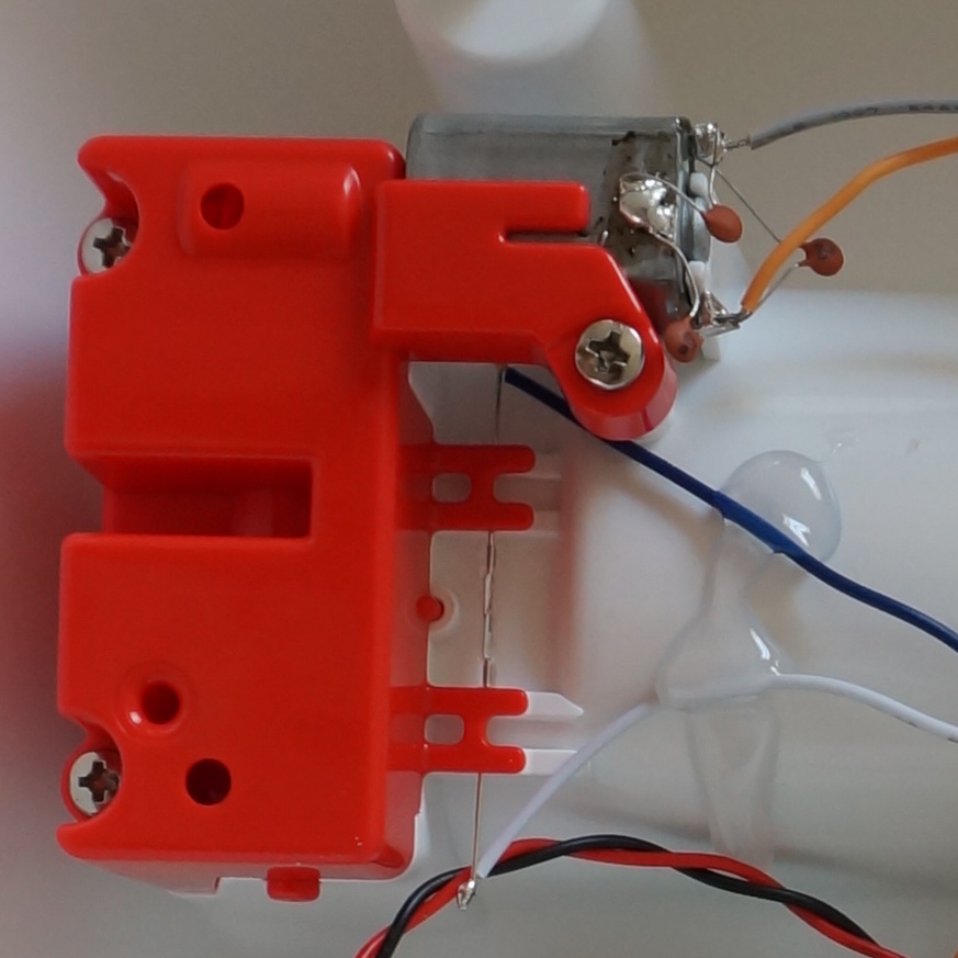
To touch one other small mechanical consideration. They are not designed to take any axial load at all, or really even any radial load either. Most of them have a plastic or aluminum bronze bushing, press-fit into a simple stamped steel body. So if you design a gearbox for one of these be sure to put as little force as possible on the bearing surfaces. If you’ve ever taken apart a small toy you’ve likely noticed that the motor can slide back and forth a bit in its mounting. This is why.
Lastly, because most of these motors are just not intended to run anywhere near their written maximum specifications it is best to assume that their specifications are a well intentioned but complete lie. Most designs work with the bottom 25% of the max number written on the spreadsheet. Running the motor anywhere near the top is usually guaranteed to brick it over time.
These are useful and ubiquitous motors, but unlike their more powerful cousins they have their own set of challenges to work with. However, considering you can buy them by the pound for cheaper than candy, there’s a good reason to get familiar with them.


The secret fount of knowledge for motors like this is old slot car hobbyist publications and articles.
Everything I know about these motors, I learned from slot car magazines in the ’60s.
Whoa, 1.5 billion units per year is a huge number, even for candies.
“1.2 milliwatt per rotation”
Why must people insist on writing articles purporting to explain electrical topics, and then fill them with meaningless statements like this that don’t add any clarity to the subject and just confuse readers? It “seems like an odd sort of unit” because the quantity is wrong. What I suspect you’re trying to say is “1.2mW per rotation per second” which at least makes physical sense, but
– is also a completely unrelatable unit that doesn’t really tell you anything
– implies power decreases linearly with RPM, which ignores torque completely
– is the wrong value anyway because 0.0012 * (15,000/60) = 0.3W, I think you mean 12 milliwatts per rotation per second.
“0.0012 * (15,000/60) = 0.3W”
That doesn’t make any sense either, because the output power of a DC motor at the nominal rated RPM is zero – the motor will only reach that speed when there is no load.
I thought it was OK by HaD standards and took it as power in terms of joules per time period for one rotation, or energy it takes to turn one rev. It would have been simpler as power at a given RPM.
There are two types of people in this world those who can extrapolate from incomplete data and
“which is an odd sort of unit that I’m just using for demonstration”
It’s not odd – it’s downright gobbledygook. “Power per rpm” is J/s : 1/s = J so you are making the equivalence of P = W
Small brushed DC motors achieve their maximum output power at their rated voltage at half the maximum torque and half the rated speed. The torque decreses linearily with speed.
http://m.eet.com/media/1178417/bldcfig5.jpg
A typical design runs the motor above half the nominal speed because any increase in load is automatically met with increasing torque and power. The motor self-regulates. Below half-speed, an increase in power demand results in a stall. That also means you only have have half the rated torque available – at maximum – trying to design around that point will still stall the motor if the load increases for any reason.
I didn’t really think about it before, but that certainly explains why all the speed settings below half on my cheap dremel knockoff are absolutely useless.
Cheap dremels often run so-called universal motors which have yet different torque-speed curves.
http://www.geocities.ws/dushang2000/Lathe%20Motors/Speed-torque%20curve%20of%20universal%20motor.jpg
This one is DC perm magnet like last century dremels.
Besides, it doesn’t really work like that. When you change the speed setting of the cheap dremel clone, you are changing the effective voltage across the motor, and/or the impedance of the power source that is supplying the motor, so it’s a whole other set of equations. Instead of changing the load curve, you’re changing the power curve.
Given that the motor has a characteristic impedance Z and the Ohm’s law becomes V=ZI and you’re changing the V part of the equation, the power of the motor becomes P=V^2/Z and that means reducing the voltage to half drops your motor’s power to a quarter.
In another case, if you’re controlling the motor via a rheostat (a resistor), the power becomes P=V^2/(Z + R) and again we note a non-linear relationship that goes approximately 1/R which produces a similiar effect.
My thoughts exactly (also, apart from the units being wrong and the concept being misleading about the way DC motors operate, the number itself is wrong by a factor of 10). I like your torque-power curve though, do you have one that illustrates input electrical power vs. output mechanical power?
Here’s a decent one from Ampflow:
http://www.ampflow.com/A28-400_Chart.png
The magenta is the efficiency curve.
As an example, you could imagine that you’re turning an air pump with your motor. The faster you pump it, the more power it takes in a linear relationship, so you draw a line for the load from the origin and see where it intersects the power curve. That’s how fast the motor can turn the pump.
So imagine next that someone pinches on the tube and makes it harder to pump the air. Maybe a leaf got stuck on the filter – same effect. The load line rises up more steeply now and the intersection moves to the left. If the original intersection was already on the left side of the maximum power point, the new intersection will move rapidly towards 0 RPM and the motor stalls easily.
Same thing happens for all sorts of mechanisms – at some point in the future the hinges will start to stick and gears and threaded rods will lose their grease etc. and the load curve gets steeper, and if you designed the mechanism for the maximum power for the motor or vice versa, i.e. the load curve intersects somewhere near the maximum power point of the motor, the whole thing starts to move like molasses.
That’s why a good rule of thumb is to de-rate a DC motor so you end up somewhere around 75% the maximum speed and a quarter of the torque, hence half the rated power. For maximum energy efficiency, 85% of the maximum speed is a good guess
Your comments on the speed effects on motors is correct, but pumps and fans and compressors don’t behave linearly.
Fan power increases with the cube of rpm – http://www.engineeringtoolbox.com/fan-affinity-laws-d_196.html
At least sliding or rolling resistance usually do.
Brilliant! Thank you, Dax
“Things I’d like to see but can probably not be bothered to hack up myself” #353 …
It’d be sort of cool to get a mass load of those motors and 3D print a large reverse planetary type geartrain, that they are all driven by, and drive it with some kind of wind rotor (Savonius, eggbeater, blades, whatever takes your fancy) for minimal power generation. IDK if you get 6-8 series packs of 3 in parallel you miiiight be able to trickle charge an e-bike.
i stopped reading at “a mere 1.2 milliwatt per rotation” . Does hackaday not have copy editors?
That has been an inherent feature of HaD since the beginning. Keeps the intelligent amused.
Plus Patent #82392382 Hackaday Crowd Sourced proof reading… ;-)
Ahhh that takes me back. I still remember the smell of ozone and burning copper from these small brushes.
(Granted, I probably used a much higher voltage than specified. But as long as the sparks don’t leave the enclosure it’s ok right? :) )
Ah (:
I love the smell of ozone in the morning (:
And accidentally using a motor as a contact speaker.
Does anyone know of a good cheap source for the DC motors out of the old Tyco 9.6V RC cars?
They had 20mm long brass gear.
Other old Tyco 9.6V cars at the thrift store.
I was trying to avoid that. ;D
This may sound weird, but I once got a whole box of old dildos really cheap…
may?
Refurbished?
So you’re the one who stole the box!
No, seriously. I saw a late night program about an actual online erotic shop on TV, where they ran a publicity campaign for people to return used vibrators for discount vouchers, and they were supposed to be recycled but someone stole the box. Someone just nicked a cubic yard of old dildos.
“If you’ve ever taken apart a small toy you’ve likely noticed that the motor can slide back and forth a bit in its mounting. This is why”
Most of those motors actually have no thrust bearings. There’s just a tiny thin PTFE washer between rotor and the housing. The rotor is free to move back and forth because it’s centered by the magnets, and so you can’t push the axle on the end – that’ll jam the motor pretty quickly. If you want a worm gear on the output, you need to add a thrust bearing to it or find a motor that has one – using a random generic small DC motor is just a bad idea.
But the real reason why the motors are loosely fit instead of screwed down is that the gears and pulleys are often made with very sloppy manufacturing tolerances and half the assembled units would bind and jam, or become impossible to put together if the motor couldn’t move to accomodate. It’s got nothing to do with the bearings on these motors.
The motors in fact do have mounting holes for screws at the front, which is how they’re meant to be attached. Of course if you put too much sideways load on the axle it will eventually wear out, but you have to put so much load on it that the friction in the bearings themselves start to bog down the motor and that’s never a good design to start with.
They also have holes molded in the back housing for screws as well.
I’d hedge to say “meant to be attached” when for reasons mentioned here and above nearly everyone chooses not to mount using those holes. Plus many of these can motors don’t have any holes. ex. https://www.pololu.com/product/1117
Also, it can be both tolerance and force on the motor reasons for mounting a motor loosely. I mean, if you did use the screws to mount the motor you’d have to be extra careful not to put an unwanted moment on the axle. You’d have suddenly taken away every degree of freedom it had to wiggle and align itself and there better be a good reason. Plus, why would you spend a couple cents on very tiny and short screws and more on touch time trying to get an eagle-eyed worker in an assembly line to install them when you could just get it for free in your injection mold/stamping/etc with a bit of cleverness?
It depends on what you’re doing. Attaching the motor loosely will also mean that your gears end up mis-aligned and they make more noise and wear out faster, so you get what you pay for.
The screwholes are there because it’s common to build a gear train between two sheets of metal or plastic, and that’s the simplest way to attach the motor to it. You don’t necessarily need to use screws – you can use two studs that simply fit the holes and sandwich the motor in somehow else. The screws would be simpler and more secure though.
“trying to get an eagle-eyed worker in an assembly line to install them”
Just depends on whether you’re making a precision product or some ching-chong toy. If it’s meant to cost $2 per unit in retail then do whatever, but if it’s meant to cost $200 then you can afford a machine to automatically screw those parts in.
I think, your last sentence exactly hits the point: Screws and screw mounting is expensive.
FYI:
Back in the old days of 8-track tapes
(geezer mode: ON)
We would often find a 12 volt DC permanent magnet motor that was stuck.
We would disassemble it and re-lubricate its bearings and re-install it.
But, the tape would play slow!
I think it was because the motor windings, or the magnets themselves, were damaged by the heat of the stalled motor.
Replacement was the only real fix.
(geezer mode: OFF/maybe)
Years ago my supervisor told me of rewinding the motors in his slot cars for more speed/power.
So what did he do, put them on the track backwards?
He rewound the motors with a thicker gauge of wire. Less resistance, more current…
dad the engineer went to the slot track with me and went home and came up with brakes for my slot car. my controller plugged a box with two cells in reversed polarity. when I let all the way off ,it shot reversed voltage to the motor and It slowed a bunch quicker for the corners before everyone else and could dive way into them. everyone else would just fly off the track. fun times
I learned something interesting trivia over the weekend: Bill Lear, the creator of Lear Aircraft, also invented the 8-track tape play. I have fond memories of my 8-track tapes so fellow geezer here :-)
Some magnets loose some of their magnetism when removed from the magnetic circuit that the motor’s construction creates. Older stepper motors are prime examples. These magnets are magnetised after assembly, or with a magnetic shunt shim that is removed after assembly. We had some of these motors that required some maintenance work, a single winding placed around one of the coils and a thump from a massive bank of capacitors was used to re charge the permanent magnets. Another possible cause of the slow motors you were experiencing, is carbon build-up in between the brushes. that can simply be blown out with high pressure air.
There are also Halbach arrays in some motors that use frustrated magnet assemblies to cancel and amplify the field in particular directions. If you pull the assembly apart, the individual magnets aren’t that strong.
If the assembly overheats or experiences a strong shock, it tends to scramble.
The original article – seems kind of anti-hacker, didn’t it? More don’ts than do’s. Dax and other commenters, thanks much for the additional info.
Most of my pre-teen hacking involved electric motors (with/without the toys they came with). One of the highlights of that period was making a functioning (if useless) electric motor from a pine board, half a dozen paperclips, some magnet wire, tape, thumbtacks. I think it came from a Time-Life science book in the 60s.
Anyway, salvaging and reusing electric motors is not much different from salvaging any other parts: try to save as much of the whole drivetrain as possible and use it at close to the original voltage.
I used to get little science kits as presents from family – the crystal radio was a favorite, and I remember falling asleep to AM every night – but I also fondly remember the “Build a Motor” kit. You can find them on Amazon or whatever now, they all look something like this:
http://www.hometrainingtools.com/media/catalog/product/cache/1/image/9df78eab33525d08d6e5fb8d27136e95/E/L/EL-KIT02.jpg
Great way to learn about brushed motor operation. The one I had spun a little plastic propeller on the back, and came with a “boat” shell to hold it, which made it actually useful and more fun.
My god, HaD. Can you please just *not* publish such blatant nonsense? It adds nothing, it’s full of incorrect and nonsensical statements and it will confuse and mislead anyone who might have otherwise been able to learn something about whatever it is you’re talking about.
I’m OK with there being learning-fundamentals articles here instead of just hacks, but this is bad. Really bad.
here’s something for a hack with these little motors, staples, good for use as a brush, had to repair one, had nothing for brushes, so i found the next best thing in a magazine… the staples holding it together.
Those little brushed “coreless” motors in micro-quadcopter are interesting too, unfortunately I know nothing about them. They can however last very long even when taking a beating (then again a single well aimed hit can take them out too), despite using even thinner wire and getting hot relatively often. Their shafts also have that slack even though the manufacturing is very precise.
While we are talking motors, does anyone know if it’s possible to buy hard drive motors? Basically I’m after a high rpm motor with a very low height.
“Metal contacts also have much lower friction than carbon or graphite brushes”
Is this correct? I haven’t done any research but my instinct is that the opposite would be true.
I know I could just look up friction coefficients but that wouldn’t help me figure out where my misconception came from.
Doesn’t graphite self-lubricate? (this is also ignoring that carbon is graphite is a metal, but that’s just semantics not anything important)
Graphite is a dry lubricant.
Carbon is not necessarily graphite. The carbon brushes are sintered together from carbon dust, sometimes with copper powder, and then heat treated to transform some of the carbon into graphite. Graphite by itself would be too soft for wear.
I have always wanted to know what the brushes are made of. Books usually say graphite (I doubt there is enough graphite mined to let all the motors have graphite in them) or just a plain word “carbon”.
Diamonds and coal are also made from carbon, duh.
It looks like this thing is used. I thought about it after your reply.
https://en.wikipedia.org/wiki/Pyrolytic_carbon
Oh wow, thank you!
I actually forgot that there was synthetic graphite.
Hackaday improves
I’ve been learning about dc motors, so I appreciated the article! I didn’t realize that running a motor near the top of its written specs will wear it down over time. I’ll keep this in mind when running any sort of dc motor in the future.
I sincerely disagree with the overall impression this write-up gives of little toy motors being weak and unable to withstand being stalled. The variability is enormous in small-size toy motors. Many of them have high enough resistance windings that they can be stalled indefinitely and not get hot or burn themselves up. And a lot of the small Mabuchi motors, which are really common in toy use, do indeed have metal thrust washers on each end of the armature shaft and are quite robuts enough to attach a worm to so they can drive a gear train directly. The super-cheap, super-flimsy constitution this author ascribes to these motors is the exception in my experience, not the rule.