What are the evocative sounds and smells of your childhood? The sensations that you didn’t notice at the time but which take you back immediately? For me one of them is the slight smell of phenolic resin from an older piece of consumer electronics that has warmed up; it immediately has me sitting cross-legged on our living room carpet, circa 1975.
!["Get ready for a life that smells of hot plastic, son!" John Atherton [CC BY-SA 2.0], via Wikimedia Commons.](https://hackaday.com/wp-content/uploads/2016/12/656px-early_1950s_television_set_eugene_oregon.jpg)
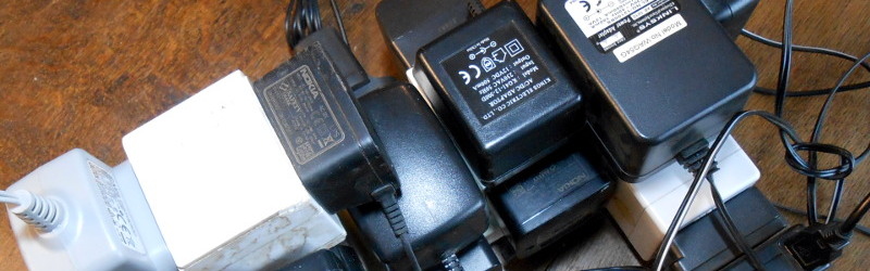
There are many small technological advancements that have contributed to this change over the decades. Switch-mode power supplies, LCD displays, large-scale integration, class D audio and of course the demise of the thermionic tube, to name but a few. The result is often that the appliance itself runs from a low voltage. Where once you would have had a pile of mains plugs competing for your sockets, now you will have an equivalent pile of wall-wart power supplies. Even those appliances with a mains cord will probably still contain a switch-mode power supply inside.
History Lesson
Mains electricity first appeared in the homes of the very rich at some point near the end of the nineteenth century. Over time it evolved from a multitude of different voltages supplied as AC or DC, to the AC standards we know today. Broadly, near to 120 V at 60 Hz AC in the Americas, near to 230 V at 50 Hz AC in most other places. There are several reasons why high-voltage AC has become the electrical distribution medium of choice, but chief among them are ease of generation and resistance to losses in transmission.
 The original use for this high-voltage mains power was in providing bright electric lighting, which must have seemed magical to Victorians accustomed to oil lamps and gas light. Over the years as electrical appliances were invented there evolved the mains wiring and domestic connectors we’re all used to, and thereafter all mains-powered appliances followed those standards.
So here we are, over a hundred years later, with both 21st century power conversion technology, and low power, low voltage appliances, yet we’re still using what are essentially 19th-century power outlets. Excuse me for a minute, I need to hire a man to walk in front of my horseless carriage with a red flag — I’m off to secure some banging tunes for my phonograph.
Given that so many of the devices we use these days have a low power consumption and accept a low voltage, surely it’s time to evolve a standard for low voltage power distribution in the home? Not to supplant the need for mains sockets entirely, after all there are times when 3 KW on tap is quite handy, but to do away with the need for all those power cubes and maybe allow the use of other low voltage sources if you have them. Does it still makes sense to send the power to our houses the 19th century way?
The Old Plugs
There will be some among you who will rush to point out that the last thing we need is Yet Another Connector System. And you’d be right, with decades of development time behind them you’d think that the connector industry would already have something for low voltage and medium power in their catalogue. The IEC60309 standard, so-called CEE-form connectors, for example has a variant for 24 V or below. Or there are connectors based on the familiar XLR series that could be pressed into service in this application. You might even be positioning USB C for the role.
Sadly there are no candidates that fit the bill perfectly. Those low-voltage CEE-forms for example are bulky, expensive, and difficult to source. And the many variants of XLR already have plenty of uses which shouldn’t be confused with one delivering power, so that’s a non-starter. USB C meanwhile requires active cables, sockets, and devices, sacrificing any pretence of simplicity. Clearly something else is required.
Oddly enough, we do have a couple of established standards for low voltage power sockets. Or maybe I should say de facto standards, because neither of them is laid down for the purpose or indeed is even a good fit for it. They have just evolved through need and availability of outlets, rather than necessarily being a good solution.
The USB A socket is our first existing standard. It’s a data port rather than a power supply, but it can supply 10W of power as 5V at 2A, so it has evolved a separate existence as a power connector. You can find it on wall warts, in wall sockets, on aeroplane seats, trains, cars, and a whole host of other places. And in turn there are a ton of USB-powered accessories for when you aren’t just using it to charge your phone, some of which aren’t useless novelties. It’s even spawned a portable power revolution, with lithium-ion battery packs sporting USB connectors as power distribution points. But 10 W is a paltry amount for more than the kind of portable devices you are used to using it with, and though the connector is fairly reliable, it’s hardly the most convenient.
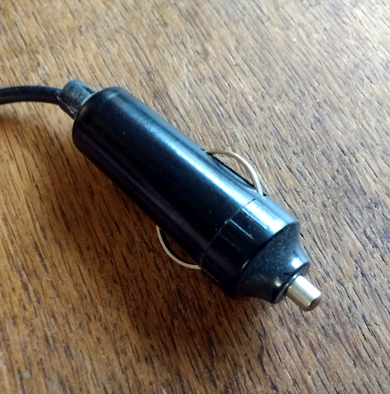
Our other existing standard is the car accessory socket. 120 W of power from 12 V at 10 A is a more useful prospect, but the connector itself is something of a disaster. It evolved from the cigarette lighter that used to be standard equipment in cars, so it was never designed as a general purpose connector. The popularity of this connector only stems from there being no alternative way to access in-car power, and with its huge barrel it is hardly convenient. About all that can be said for it is that a car accessory plug has enough space inside it to house some electronics, making some of its appliances almost self-contained.
The New Plug?
So having torn to pieces the inadequate state of existing low voltage connectors, what would I suggest as my solution? Given a blank sheet, how would I distribute low voltage?
First, it’s important to specify voltages and currents, and thus look at the power level. Where this is being written the wiring regulations do not apply to voltages under 50 V, so that sets our upper voltage limit. And while it’s tempting to pick a voltage near the top of that limit it also makes sense to stay with one more likely to be useful without further conversion. So while part of me would go straight for 48 V I’d instead remain with the familiar 12 V.
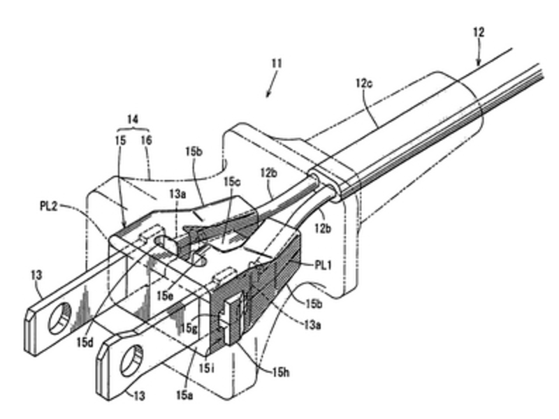
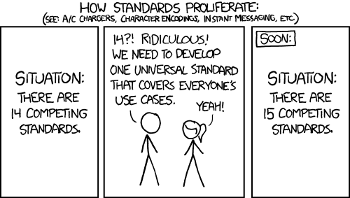
Looking at our existing 12 V standard, the car accessory socket delivers 120 W, that should be enough for the majority of low voltage lighting and appliances. So 12 V at 10 A per socket is a reasonable compromise even if the car socket isn’t. We thus need to find a more acceptable socket, and given that a maximum of 10 A isn’t a huge current, it shouldn’t be too difficult to imagine one. If I had a plug and socket manufacturer at my disposal and I was prepared to disregard the XKCD cartoon above I’d start with a fairly conventional set of pins not unlike the CEE-form connector above but without the industrial ruggedisation, and incorporate a fuse to protect the appliance cable from fire. Those British BS1363, fused-mains-plug habits die hard. In the socket surround I’d probably also incorporate a 5 V regulator for a USB outlet.
![These are best kept out of sight. Smial (Own work) [FAL], via Wikimedia Commons.](https://hackaday.com/wp-content/uploads/2016/12/atx-netzteil.jpg)
We do not however want to replace a load of wall warts with a load of switch mode PSU boxes. The point of the sockets described here is to take away other paraphernalia, not to just deliver power. Clearly some form of cabling is required. At this point there has to be a consideration of topology, will there be one cable per socket, and if not how many sockets will go on one cable? If the former then 16 A insulated flex from our distribution point with a single 10 A fuse per cable would suffice with enough margin to allow for sensible cable runs, while if the latter then something more substantial would be required. There are flexible insulated copper busbar products from the domestic low voltage lighting industry that would suffice, for example.
</rant>
This has been an epic rant, a personal manifesto if you will, for a future with slightly safer and more convenient power outlets. Somehow I don’t expect to see a low-voltage home distribution system like this emerge any time soon, though I can keep hoping.
Your vision for low-voltage power distribution may differ from mine, for example it may include some smart element which I have eschewed. You might even be a mains-voltage enthusiast. Please let us know in the comments.


I’ve thought a lot about integrating dc to the home.
The wires are already in your home. They just need to be redirected at the ac Panel.
Removed from the breaker and used as a dc circuit.
Feed them from the batteries.
The lights and switches will work the same once you change the fixture to a dc appliance.
The outlets need to change.
My thought would be to use a foreign outlet. That way the dc nature would be obvious and the product already exists..
I see all these posts that USB-C is the answer. If so then what is the question?
Isn’t the idea to have a common DC bus powered by one single switching supply rather than separate supplies for every device in the house? USB-C negotiates a voltage. That means separate supplies for each device. Ok, I guess when you build the USB-C supplies into the outlets you at least eliminate the ever-multiplying mess of wall-warts. Then again.. at least wall-warts can be plugged into a splitter (better yet a surge protector) allowing several devices to at least use the same A/C outlet. What happens when you just installed your new 6xUSB-C outlet and you realize that you now have 7 devices to plug in?
Dc distribution in the home was investigated for awhile back in the 1970’s.
It makes even more sense now, but probably better to use 48V- near the upper limit of the safety specs. This reduces wire losses within the home, yet is still relatively easy to convert to 12, 5, 3.3V. At 48V, you could easily get a few hundred watts.
A centrallized 240V AC/48V DC converter in the home would be ideal to keep efficiencies high.
What about the usual 9mm wall-wart connector? It is cheap, both sockets and plugs are readily available at varying qualities. Quite easy to imagine a wall plate that includes several of these 9mm sockets.
Since someone mentioned using military systems as an inspiration, here’s a short summary of power distribution on the International Space Station:
https://www.edn.com/international-space-station-iss-power-system/
There are surely more detailed and more up-to-date references out there (e.g. check ESA or NASA), and that article doesn’t talk about connectors. It does mention, though, using 160VDC down-converted to 120VDC for outlets in each module.
In a home, one could distribute a higher DC voltage throughout, and the have one built-in dc-dc converter per room/group of rooms to provide the desired voltage.
As mentioned, though, the best solutions spanning more than one room (where a 3D printed / custom cased multi-voltage PSU sounds nice) still seem to be 40+ VDC PoE or in-wall USB-C converters. Perhaps someone could make series of reasonably-priced USB-C to DC barrel plug (or jack) cables (one for each common voltage/current range) that could be used to replace wall wart PSUs for legacy ‘dumb’ DC devices.
If one has old POTS cabling/jacks in their home that are no longer in use, those also could be re-purposed to supply 48VDC or 24VDC (maybe this would work for the IoT example) at low power levels.