There is an old saying: “In theory, theory and practice are the same. In practice, they are not.” We spend our time drawing on paper or a computer screen, perfect wires, ideal resistors, and flawless waveforms. Alas, the real world is not so kind. Components have all kinds of nasty parasitic effects and no signal looks like it does in the pages of a text book.
Consider the following problem. You have a sine wave input coming in that varies between 0 V and 5 V. You want to convert it to a square wave that is high when the sine wave is over 2.5 V. Simple, right? You could use a CMOS logic gate or a comparator. In theory…
The problem is, the sine wave isn’t perfect. And the other components will have little issues. If you’ve ever tried this in real life, you’ll find that when the sine wave is right at the 2.5 V mark the output will probably swing back and forth before it settles down. This is exacerbated by any noise or stretching in the sine wave. You will wind up with something like this:
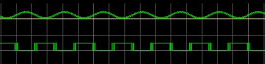
Notice how the edges of the square wave are a bit fat? That’s the output switching rapidly back and forth right at the comparator’s threshold.
Hysteresis
The answer is to not set the threshold at 2.5 V, or any other single value. Instead, impose a range outside of which it will switch, switching low when it leaves the low end of the range, and high when it exceeds the high end. That is, you want to introduce hysteresis. For example, if the 0 to 1 shift occurs at, say, 1.9 V and the 1 to 0 switch is at 0.5 V, you’ll get a clean signal because once a 0 to 1 transition happens at 1.9 V, it’ll take a lot of noise to flip it all the way back below 0.5 V.
You see the same effect in temperature controllers, for example. If you have a heater and a thermal probe, you can’t easily set a 100 degree set point by turning the heater off right away when you reach 100 and then back on again at 99.9999. You will usually use hysteresis in this case, too (if not something more sophisticated like a PID). You might turn the heater off at 99 degrees and back on again at 95 degrees, for example. Indeed, your thermostat at home is a prime example of a system with hysteresis — it has a dead-band of a few degrees so that it’s not constantly turning itself on and off.
Schmitt Triggers and How to Get One
A Schmitt Trigger is basically a comparator with hysteresis. Instead of comparing the incoming voltage with VCC / 2, as a simple comparator would, it incorporates a dead band to ensure that logic-level transitions occur only once even in the presence of a noisy input signal.
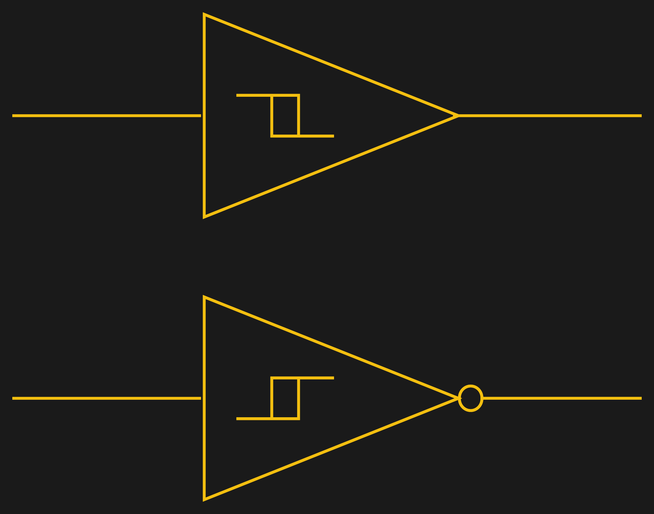
Assuming you want a Schmitt trigger in a circuit, you have plenty of options. There are ICs like the 74HC14 that include six (inverting) Schmitt triggers. On a schematic, each gate is represented by one of the symbols to the right; the little mark in the box is the hysteresis curve, and the little bubble on the output indicates logical negation when it’s an inverter.
You can also make them yourself out of transistors or even a 555 chip. But the easiest way by far is to introduce some feedback into a plain op amp comparator circuit.
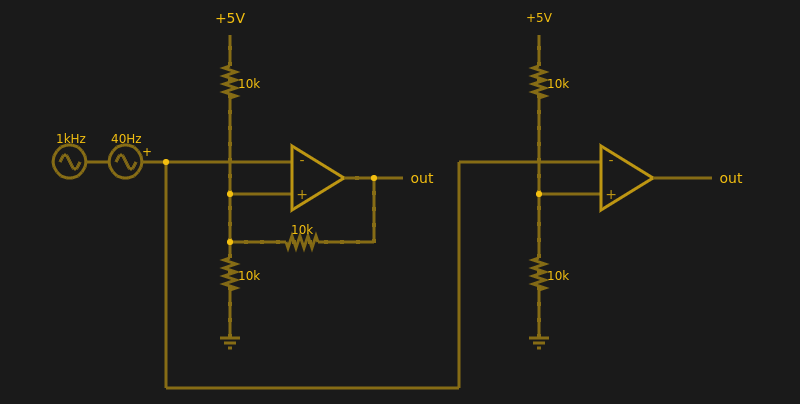
Below are two op amps, one with some positive feedback to make it act like a Schmitt trigger. The other is just a plain comparator. You can simulate the design online.
If you haven’t analyzed many op amp circuits, this is a good one to try. First, imagine an op amp has the following characteristics:
- The inputs are totally open.
- The output will do whatever it takes to make the inputs voltages the same, up to the power supply rails.
Neither of these are totally true (theory vs. practice, again), but they are close enough.
The comparator on the right doesn’t load the inputs at all, because the input pins are open circuit, and the output swings to either 0 V or 5 V to try, unsuccessfully, to make the inputs match. It can’t change the inputs because there is no feedback, but it does make a fine comparator. The voltage divider on the + pin provides a reference voltage. Anything under that voltage will swing the output one way. Over the voltage will swing it the other way. If the voltages are exactly the same? That’s one reason you need hysteresis.
The comparator’s voltage divider sets the + pin to 1/2 the supply voltage (2.5 V). Look at the Schmitt trigger (on top). If the output goes between 0 V and 5 V, then the voltage divider winds up with either the top or bottom resistor in parallel with the 10K feedback resistor. That is, the feedback resistor will either be connected to 5 V or ground.
Of course, two 10K resistors in parallel will effectively be 5K. So the voltage divider will be either 5000/15000 (1/3) or 10000/15000 (2/3) depending on the state of the output. Given the 5 V input to the divider, the threshold will be 5/3 V (1.67 V) or 10/3 V (3.33 V). You can, of course, alter the thresholds by changing the resistor values appropriately.
Practical Applications
Schmitt triggers are used in many applications where a noisy signal requires squaring up. Noisy sensors, like an IR sensor for example, can benefit from a Schmitt trigger. In addition, the defined output for all voltage ranges makes it handy when you are trying to “read” a capacitor being charged and discharged. You can use that principle to make a Schmitt trigger into an oscillator or use it to debounce switches.
If you want to see a practical project that uses a 555-based Schmitt, check out this light sensor. The Schmitt trigger is just one tool used to fight the imprecision of the real world and real components. Indeed, they’re nearly essential any time you want to directly convert an analog signal into a one-bit, on-off digital representation.


“””The comparator (bottom)””” where is there a vertical image showing a comparator? The immediately adjacent image is laid out horizontally… so do you mean (left) or (right)?
Yep, I edited that image… I’ll fix up the text. Thanks!
Check the link to the falstad sim :)
Check the link to the falstad sim :)
My favorite implementation of the schmitt trigger is with pulse width modulation. When a triangle wave is provided in on the non-inverting input and a variable voltage (potentiometer or other source) is provided to the non-inverting input, the output is a pulse width modulation that is proportional to the input voltage. Very handy for power supplies and controlling servos.
In practice op-amps work like crap for this application because they tend to get stuck near the supply rails and take their sweet time to switch states. The work faster when the output transistors are not in saturation.
For reference:
http://www.radio-electronics.com/info/circuits/opamp_comparator/op_amp_comparator.php
The difference: op-amps are designed to operate in closed loop, whereas comparators are designed for open loop. When op-amps are used in open loop, they work like crap.
That’s why, if you pick a common “easy” op-amp like an LM258 and try to make a schmitt-trigger out of it, it’ll start behaving poorly even at audio frequencies. The 555 version will be much more precise and faster because the internals are comparators instead of op-amps.
I got bitten by that trying to make an analog function generator. The peaks of the triangle waves started doing all sorts of weird frequency dependent things over 2 kHz because the damn thing wouldn’t switch states, and a sawtooth wave was almost impossible – everything worked fine in the simulator, the actual thing was non-linear as heck with an op-amp that was “supposed” to work to several MHz.
Though if you have to use op-amps, then you can put a small speed-up capacitor in the positive feedback path in parallel to the resistor. It forms an RC highpass circuit with the voltage divider used in the example. That way you can push the frequency response up by narrowing the hysteresis for higher frequency signals (steep signal edges) to compensate for the sluggishness of the op-amp.
It’s still no good if you want the schmitt-trigger to trigger at a steady voltage, but for things like cleaning up a noisy digital signal it may help. Yet, there’s still a big lag to when the op-amp output signal actually starts to switch from high to low because it takes time to (dis)charge all sorts of junction capacitances which I don’t fully understand.
The same issues apply for making a PWM signal with an op-amp, though if you’re controlling a servo or dimming a LED the frequency will be low enough that it won’t matter. If you want to make a whine-free PWM motor controller above 20 kHz then it starts to go non-linear again.
Trigger warning.
it had to be you… otherwise it would have been me :)
As an ME who never understood what the hell was going on in this chapter of my EE courses, you just helped me understand. Thank you for explaining more clearly than Dr. Feinberg did so many years ago.
Yes, Dr. Feinberg did always seem to get triggered by Dr. Schmitt and end up making extreme choices when the decision really should have been anywhere but in the middle ground.
Dr. Howard, Dr. Fein, and Dr. Howard used be triggered by the slightest misunderstandings. (They were always represented in court by Dewey, Cheatham, and Howe.)
The thing to remember here is that Schmitt triggers *still* don’t like signals in the hysteresis voltage range. In that range, they draw way more current (labelled ‘delta-Icc’ in datasheets) than in the ‘valid’ voltage ranges.
Good article.
Alternate title could be: “What the Schmitt?”
Or “Great Schmitt”
Schmitt happens
I’ve built robots that use crude “nerve” models based on Schmitt triggers. “Spyder” used 16 of them. It was simply a crude RC circuit paired to a Schmitt trigger. A charge would build, and the pulse would propagate from one node to the next. It had a central pattern generator and 4 branches leading off of that central core to generate the walking gait.
http://www.dailymotion.com/video/x1d65em
One time I tried an experiment with a thermistor, a spotlight, a solid state relay, and a potentiometer (volume knob). The result was that noisy swuare-ish waveform at about 1/5 Hz. The bulb came on at the start, flicker, cut off, flicker, come on, back and forth. A heater with suitable frequency response like the spotlight could get away with little or no hysteresis, but real life dictates otherwise. That above experiment with hysteresis added would lengthen the life of the bulb and still have tight control of the temperature at the thermistor if carefully designed. I tried that experiment out of curiosity just for fun.
Your Op Amp example is not good for a lot of reasons. One reason is running the second op amp open loop. That’s just asking for trouble. Some poor “Maker” is going to breadboard your example using some miscellaneous “popcorn” junk box op amps and end up pulling his or her hair out trying to make it work.
Other reasons to avoid op amps as comparators include slow speed, power consumption (especially when banging the rails), phase inversion at the rails (amongst a host of other bad overload effects that add up), and more. An experienced Engineer will understand how to avoid these pitfalls. A Maker – maybe not.
At least when touting op amps as comparators to a mixed audience, please mention some or the potential problems/trade-offs, and recommend the use of closed-loop unity-gain-stable voltage (not current) feedback op amps.
Well, I think people have read too much into that. This wasn’t a how to, it was a how about, if I can coin that phrase. The point is what is Schmitt trigger and why do I want one. I didn’t want to go into the nuances between an op amp and a comparator (which is an op amp optimized for that service).I didn’t show the power connections to the op amps. I didn’t show decoupling capacitors for that power supply. I didn’t go into not being able to go to the rails or input offset or the effect of gain/bandwidth product or…. all the other things I might have if this had been a post about designing anything with opamps. My point was to show in simulation what happens when you feed a slow rising input into a logic gate and how to employ hysteresis.