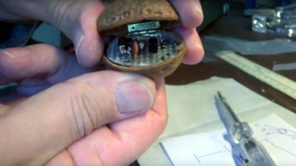
What’s the minimal BOM for a working amateur radio transmitter? Looks like you can get away with seven parts, or eight if you include the walnut. You’ve got to have a walnut.
Some hams really love the challenge of QRP, or the deliberate use of low-power transmitters to provide a challenge to making long-distance contacts. We’ve covered the world of QRP before and noted that while QRP rigs don’t throw a lot of power, it doesn’t mean that they need to be simple. Some get quite complex and support many different modulation schemes, even digital modes. With only a single 2N3904 transistor, [Jarno (PA3DMI)]’s tiny transmitter won’t do much more than send Morse using CW modulation, but given that it’s doing so from inside a walnut shell, we have no complaints. The two halves of the shell are hinged together and hold a scrap of perfboard for the simple quartz crystal oscillator. The prototype was tuned outside the shell, and the 9-volt battery is obviously external, but aside from that it’s nothing but nuts.
We’d love to see [Jarno] add a spring to the hinge and contacts on the shell halves so no keyer is required. Who knows? Castanet-style keying might be all the rage with hams after that.
As much as we’d like to have the right tools for the right job all of the time, sometimes our parts drawers have other things in mind. After all, what’s better than buying a new tool than building one yourself from things you had lying around? That’s at least what [Saulius] must have been thinking when he needed a thermometer with a digital output, but only had a dumb, but feature-rich, thermometer on hand.
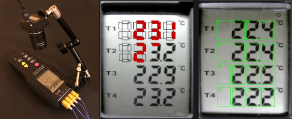
Luckily, [Saulius] had a webcam lying around as well as an old thermometer, and since the thermometer had a LCD display it was relatively straightforward to get the camera to recognize the digits in the thermometer’s display. This isn’t any old thermometer, either. It’s a four-channel thermometer with good resolution and a number of other useful features (with an obvious lack of communications abilities), so it’s not something that he could just overlook.
Once the camera was mounted to an arm and pointed at the thermometer’s screen, an algorithm running on a computer detects polygons and reports its information into a CSV file. This process is made simpler by the fact that LCD screens like this are very predictable. From there, the data is imported into LibreOffice and various charts and graphs can be made.
Although perhaps not the most elegant of hacks, sometimes you have to work with the supplies that are on hand at the time. Sometimes the tools you need are too expensive, politically dangerous, or too impractical to obtain. To that end [Saulius]’s hack is a great example of what hacks are possible with the right mindset.
Over on YouTube, [GumpherDM3] built one of the greatest musical projects we’ve seen in a long time. It’s an analog synthesizer that is one of a kind. It’s going to stay one of a kind, too: no one would ever want to copy this mess of wires and perfboard that was successfully turned into a complete musical instrument.
The design of this synth is what you would expect from something that draws its inspiration from semimodular synths such as the Minimoog and Korg MS20. There are four VCOs on this synth, two audio and two used for the LFOs. A four-pole low pass filter, VCA, and two envelope generators round out the purely analog portion of the build. There’s an arpeggiator in there too, which makes for a really great demo video (below).
Inside, this is a true analog synth with the VCOs, filter, and VCA built around the LM13700 transconductance amplifier. The build log shows these chips spread out around half a dozen breadboards before being plugged into sockets soldered to handwired perf board. This synth is a one of a kind instrument – no one would want to build this thing twice.
Additional features include an Arduino with a MIDI in port sending out CV signals to the analog part of the synth. This thing has everything you would expect from a modern take on an analog synthesizer, and it sounds good, too.
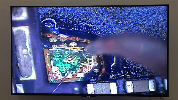
If you can’t, fear not – someone can, and we found him or her courtesy of a video that [Bunnie Huang] tweeted a while back. There’s not much information in the video, but from what we can gather it comes from an outfit called G-Lon Technology in Guang Zhou. Their Facebook page suggests that they teach cellphone repair, and if they take their repairs this far, we’d say the students are getting their tuition’s worth.
The reason for the repair is unclear, although the titles refer to a “CPU to U0301 AP31 AR31 broken repair,” which we take to refer to a boot error that can be repaired by exposing a couple of pads inside the CPU and wiring them to another chip. We’d love to hear comments from anyone familiar with the repair, but even in the absence of a clear reason for undertaking this, the video is pretty impressive. The epoxy cap of the CPU is painstakingly ground away under a microscope, then tiny tools are used to scrape down to the correct layers. Solder mask is applied, hair-thin wires are tacked to the pads, and a UV-curing resin is applied to fill the CPU’s new gaping hole and to stabilize the wires. It seems like a lot of work to save an iPhone, but it sure is entertaining to watch.
Can’t get enough of poking around the innards of chips? We’ve got decapping stories aplenty: one, two, and three that you might like. We’ve even covered at least one CPU internal repair before too.
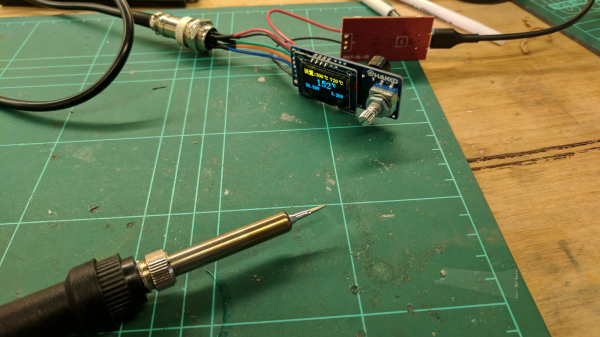
Some time back we ran a post on those cheap USB soldering irons which appeared to be surprisingly capable considering they were really under powered, literally. But USB Type-C is slated to change that. Although it has been around for a while, we are only now beginning to see USB-C capable devices and chargers gain traction. USB-C chargers featuring the USB-PD option (for power delivery) can act as high power sources allowing fast charging of laptops, phones and other devices capable of negotiating the higher currents and voltages it is capable of sourcing. [Julien Goodwin] shows us how he built a USB-C powered soldering iron that doesn’t suck.
He is able to drive a regular Hakko iron at 20 V and 3 Amps, providing it with 60 W of input power from a USB-C charger. The Hakko is rated for 24 V operating voltage, so it is running about 16% lower power voltage. But even so, 60 W is plenty for most cases. The USB-C specification allows up to 5 A of current output in special cases, so there’s almost 100 W available when using this capability.
It all started while he was trying to consolidate his power brick collection for his various computers in order to reduce the many types and configurations of plugs. Looking around, he stumbled on the USB-PD protocol. After doing his homework, he decided to build a USB Type-C charger board with the PD feature based on the TI TPS65986 chip – a very capable USB Type-C and USB PD Controller and Power Switch. The TI chip is a BGA package, so he had to outsource board assembly, and with day job work constantly getting in the way, it took a fair bit of time before he could finally test it. Luckily, none of the magic smoke escaped from the board and it worked flawlessly the first time around. Here is his deck of slides about USB-C & USB-PD [PDF] that he presented at linux.conf.au 2017 Open Hardware Miniconf early this year. It provides a nice insight to this standard, including a look at the schematic for his driver board.
Being such a versatile system, we are likely to see USB-C being used in more devices in the future. Which means we ought to see high power USB Soldering Irons appearing soon. But at the moment, there is a bit of a “power” struggle between USB-C and Qualcomm’s competing “Quick Charge” (QC) technology. It’s a bit like VHS and Betamax, and this time we are hoping the better technology wins.
There is an old saying: “In theory, theory and practice are the same. In practice, they are not.” We spend our time drawing on paper or a computer screen, perfect wires, ideal resistors, and flawless waveforms. Alas, the real world is not so kind. Components have all kinds of nasty parasitic effects and no signal looks like it does in the pages of a text book.
Consider the following problem. You have a sine wave input coming in that varies between 0 V and 5 V. You want to convert it to a square wave that is high when the sine wave is over 2.5 V. Simple, right? You could use a CMOS logic gate or a comparator. In theory…
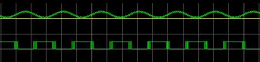
The problem is, the sine wave isn’t perfect. And the other components will have little issues. If you’ve ever tried this in real life, you’ll find that when the sine wave is right at the 2.5 V mark the output will probably swing back and forth before it settles down. This is exacerbated by any noise or stretching in the sine wave. You will wind up with something like this:
Notice how the edges of the square wave are a bit fat? That’s the output switching rapidly back and forth right at the comparator’s threshold.
Hysteresis
The answer is to not set the threshold at 2.5 V, or any other single value. Instead, impose a range outside of which it will switch, switching low when it leaves the low end of the range, and high when it exceeds the high end. That is, you want to introduce hysteresis. For example, if the 0 to 1 shift occurs at, say, 1.9 V and the 1 to 0 switch is at 0.5 V, you’ll get a clean signal because once a 0 to 1 transition happens at 1.9 V, it’ll take a lot of noise to flip it all the way back below 0.5 V.
You see the same effect in temperature controllers, for example. If you have a heater and a thermal probe, you can’t easily set a 100 degree set point by turning the heater off right away when you reach 100 and then back on again at 99.9999. You will usually use hysteresis in this case, too (if not something more sophisticated like a PID). You might turn the heater off at 99 degrees and back on again at 95 degrees, for example. Indeed, your thermostat at home is a prime example of a system with hysteresis — it has a dead-band of a few degrees so that it’s not constantly turning itself on and off.
Schmitt Triggers and How to Get One
A Schmitt Trigger is basically a comparator with hysteresis. Instead of comparing the incoming voltage with VCC / 2, as a simple comparator would, it incorporates a dead band to ensure that logic-level transitions occur only once even in the presence of a noisy input signal.
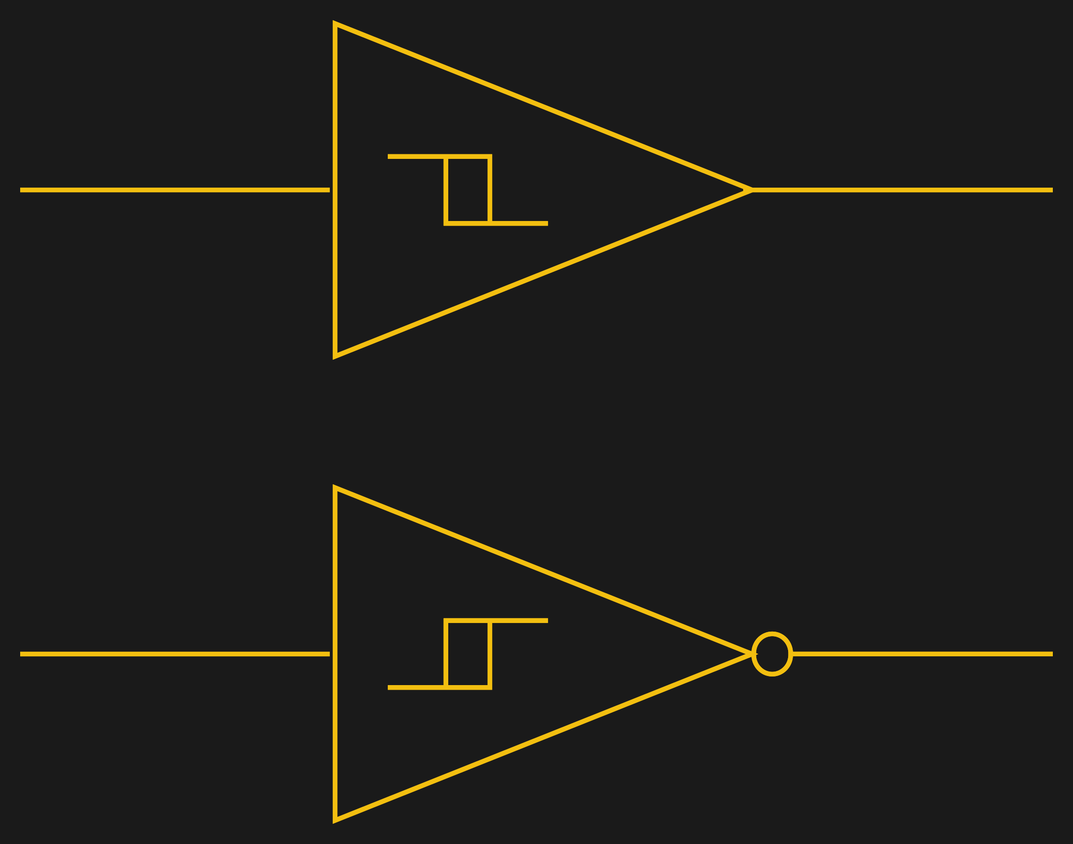
Assuming you want a Schmitt trigger in a circuit, you have plenty of options. There are ICs like the 74HC14 that include six (inverting) Schmitt triggers. On a schematic, each gate is represented by one of the symbols to the right; the little mark in the box is the hysteresis curve, and the little bubble on the output indicates logical negation when it’s an inverter.
You can also make them yourself out of transistors or even a 555 chip. But the easiest way by far is to introduce some feedback into a plain op amp comparator circuit.
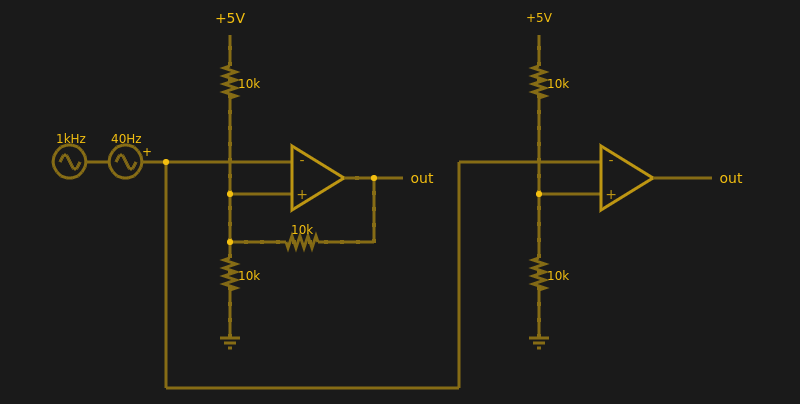
Below are two op amps, one with some positive feedback to make it act like a Schmitt trigger. The other is just a plain comparator. You can simulate the design online.
If you haven’t analyzed many op amp circuits, this is a good one to try. First, imagine an op amp has the following characteristics:
The inputs are totally open.
The output will do whatever it takes to make the inputs voltages the same, up to the power supply rails.
Neither of these are totally true (theory vs. practice, again), but they are close enough.
The comparator on the right doesn’t load the inputs at all, because the input pins are open circuit, and the output swings to either 0 V or 5 V to try, unsuccessfully, to make the inputs match. It can’t change the inputs because there is no feedback, but it does make a fine comparator. The voltage divider on the + pin provides a reference voltage. Anything under that voltage will swing the output one way. Over the voltage will swing it the other way. If the voltages are exactly the same? That’s one reason you need hysteresis.
The comparator’s voltage divider sets the + pin to 1/2 the supply voltage (2.5 V). Look at the Schmitt trigger (on top). If the output goes between 0 V and 5 V, then the voltage divider winds up with either the top or bottom resistor in parallel with the 10K feedback resistor. That is, the feedback resistor will either be connected to 5 V or ground.
Of course, two 10K resistors in parallel will effectively be 5K. So the voltage divider will be either 5000/15000 (1/3) or 10000/15000 (2/3) depending on the state of the output. Given the 5 V input to the divider, the threshold will be 5/3 V (1.67 V) or 10/3 V (3.33 V). You can, of course, alter the thresholds by changing the resistor values appropriately.
Practical Applications
Schmitt triggers are used in many applications where a noisy signal requires squaring up. Noisy sensors, like an IR sensor for example, can benefit from a Schmitt trigger. In addition, the defined output for all voltage ranges makes it handy when you are trying to “read” a capacitor being charged and discharged. You can use that principle to make a Schmitt trigger into an oscillator or use it to debounce switches.
If you want to see a practical project that uses a 555-based Schmitt, check out this light sensor. The Schmitt trigger is just one tool used to fight the imprecision of the real world and real components. Indeed, they’re nearly essential any time you want to directly convert an analog signal into a one-bit, on-off digital representation.
Hackaday and Tindie will be at SCALE Friday through Sunday, showing off the coolest parts of Hackaday, Hackaday.io, and our lovable robotic dog, Tindie. We’ll be handing out t-shirts and stickers, and we’ll be giving tours of the SupplyFrame Design Lab located just two blocks away from the convention center. The Design Lab is a crown jewel of our corporate overlord’s emphasis on Open Hardware, and if you want to see where the magic happens, this is your chance. We’ll be running tours of the Lab on Friday, so find the Hackaday and Tindie crew in the expo area around 3:40 PM.