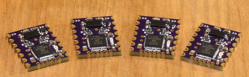
[Blecky]’s entry to the Hackaday Prize is MappyDot, a tiny board less than a square inch in size that holds a VL53L0X time-of-flight distance sensor and can measure distances of up to 2 meters.
MappyDot is more than just a breakout board; the ATMega328PB microcontroller on each PCB provides filtering, an easy to use I2C interface, and automatically handles up to 112 boards connected in a bus. The idea is that one or a few MappyDots can be used by themselves, but managing a large number is just as easy. By dotting a device with multiple MappyDots pointing in different directions, a device could combine the readings to gain a LiDAR-like understanding of its physical environment. Its big numbers of MappyDots [Blecky] is going for, too: he just received a few panels of bare PCBs that he’ll soon be laboriously populating. The good news is, there aren’t that many components on each board.
It’s great to see open sourced projects and tools in which it is clear some thought has gone into making them flexible and easy to use. This means they are easier to incorporate into other work and helps make them a great contestant for the Hackaday Prize.


Very nice job.
Good luck on sales.
I like the concept of the device.
I think I’ll keep a eye on this. I can see some uses as time goes on.
Keep up the good work.
When will the sale begin and where?
The Tindie store is here – https://www.tindie.com/products/blecky/mappydot-micro-smart-lidar-sensor/
I hope to start shipping the first batch at the end of this month. If not, the first week of September.
whoops, that is not the price I expected.
The pricing goes down after 5 units (to $22USD). I want to eventually release these for a cheaper price if produced at a larger scale overseas, but for the moment they are being assembled and tested locally (in Australia).
It seems that in the short space of time during development, API-less VL53L0X boards (a breakout board with an easier to use API) have been released on the market and they have a retail price of $25US. The MappyDot has however been designed from scratch to be released with a 5 litre (1.32086 US gallon) bucket-load of extra “free” functionality compared these modules, all for the same price.
I’ve yet to see a range analysis of that sensor against the various surfaces it would encounter in use.
Thank you Perry, businessing things is definitely tough work :)
I’m actually really really excited to see what people end up doing with these modules apart from their advertised features and applications.
I’ve got a few designs and plans for some interesting kits in the works for these modules too. The MappyDot started as more a stepping stone for integrating into the kits to solve all the problems I had with their design. Hopefully others end up finding them useful too!
It’s a nice idea, but unfortunately, the bad PCB design will probably make it a pain to use.
Makers of circuit boards for robotics and other stuff take note: Think of how people will integrate your PCB into their design.
I see two main problems with this board. First, the castellated pads. Castellated pads are a great idea if you want to build a module that’s soldered to some other board with a reflow process. Soldering by hand is okay as well, but not as much fun. They are, however, not very suitable if you want to solder wires to them or integrate them on anything other than a custom-designed PCB to accomodate this module. However, the point of this PCB is that it integrates all the components already. It’s not rocket science (unlike power supplies or HF stuff), so why should you use the module on your own PCB instead of just designing the circuitry directly on your own board? It’s probably a reasonable project, but the choice of castellated pads is completely ununderstandable. It really makes no sense at all.
Second, the lack of mounting holes that can actually accomodate screws. I see this very often even on boards from manufacturers that should know better. The point of the lidar sensor is to measure distance to some object precisely. To this end, it needs to be aligned and stay aligned. This alignment may not always coincide with the alignment of some carrier PCB. Putting in some mounting holes allows users to install the board at some place on their robot or other device using screws.
I don’t have much experience with castellated pads. Why would they be any harder to solder a wire to than a full hole or SMD pad? For that matter, if they’re on a standard grid, what’s wrong with just using a single-row header (other than slightly less strength than through holes)? IMO, it’s a pretty cool project, and at least a satisfactory form-factor.
I find castellated pads a breeze to solder by hand, I would even say it easier than soldering in a header. I love castellated pads.
Also great if you want to solder wires to them, they great at everything you said they are bad at… well at least imho.
Agree with the mounting holes though.
The castellated pins are a standard 2.54mm (0.1″) pitch, so you can solder headers directly onto it and even use them in a breadboard. It doesn’t offer quite the same rigidity as regular holes, but it stands up to plugging and unplugging the modules during development fairly well from testing.
There is also a breakout board available with mounting holes too if you prefer that option too.
Just to add, the decision to go with castellated pins was such that you can easily create custom sized mounting options as well by adding it to any shaped mounting PCB, rather than being restricted to what it comes with. I might offer a board that is just mounting holes and say flat flex cables between it later, but really wanted to see what people came up with first.
*offer a board formfactor with mounting holes
just solder your pins in the same plane as the PCB and use much solder, it will be solid, then you can glue a socket to your robot body in the area where you want the sensor to be ;)
What do you think about this design: https://hackaday.io/project/21439-laser-proximitydistance-sensor ?
USB-CDC and UART as host-interfaces could be quite limiting if multiple such sensors are used in a single system, but I chose USB specifically so that it can be easily integrated with PC/RPi like SoC without any wiring.
I’ve just assembled the first board and there are already some changes pending for second revision, so I’m open to suggestions for improvements.
This seems to be a similar device:
http://www.teraranger.com/products/teraranger-multiflex/
Wow they look pretty slick, however they seem to have one design let down. “Update rate: Up to 50Hz for Multiflex and 30Hz for Multiflex PCB (divided by the number of sensors connected)”. The MappyDot will give you 50Hz per module for up to 5600 measurements per second on a single bus (112 MappyDots); you could theoretically do more, but you need to break I2C specifications.
While I don’t expect people to buy that many (I’ll give a HUGE discount if you do :P), even having 8 on the same bus only gives you up to 6.25Hz per Teraranger module. For gesture related applications, this can be a deal breaker for some.
Always nice to have more options, but I don’t really see the point of adding a dedicated microcontroller on here. The thing already has I2C, so now you need to manage (maintain firmware, flash, debug) another device, mainly as a fancy I2C address translator? I would much rather use something like this:
http://www.linear.com/product/LTC4316 (local address translation using solder jumpers)
or
http://www.ti.com/product/PCA9546A (4 channel i2c switch)
or…
actually after checking the datasheet you can just reconfigure the i2c address on the device (by changing the addres on one device while holding the others in reset).
Offloading the filtering and doing all sorts of gymnastics before sending the data out sounds like a good enough reason to me. The address translation is just the icing on the cake.
We don’t need yet another Arduino in a crappy form factor.
The microcontroller is completely useless, since you can solve the bus problem by changing the sensors’ I2C addresses and do all the filtering and processing on a better chip (most things you’d use these sensors for require a powerful microcontroller anyway). It only makes the module more expensive and introduces bugs and other reliability issues (such as the risk of bricking sensors by updating their firmware).
Also, the lack of mounting holes makes these modules useless for anything that requires real precision.
The issue with those sensors is that you have to wire up the extra xshut gpio lines first to change the I2C addresses (one for each sensor), so if you have many distributed sensors, you can have a pretty complicated setup. The other issue is that if you wire up few of these to the same bus, you spend a fair bit of time in upkeep, depending on your application, so you don’t get the maximum performance out of each sensor.
There’s a breakout available as well if you want to mount it. Castellated pins are always pretty polarising, I totally understand that. The decision to go with that was based on the popularity of the ESP8622 modules, however we might offer a different form factor later. The MappyDots have auto calibration, so you can recalibrate if need be after mounting.
The bootloader is very difficult to completely brick. However if you do manage to brick it somehow, just like the Arduino, a cheap $10 programmer will get you back up and running.
Not to mention if you want interrupt driven reads, then you need the interrupt line too.
A module makes sense for radios because all intentional radiators require FCC certification (or the equivilant in your jurisdiction). If you lay it out on your own PCB, you’re responsible for that. If you buy the module premade, the supplier’s already done the work for you.
It makes less sense for a module like this, where there isn’t anything special going on.
They’ve definitely done the work, but it doesn’t mean you don’t have to get FCC certification for the final assembly. Basically you don’t have to go through the design work to make sure it “should” meet FCC requirements. You still need to get the final assembly tested before selling.
All those ESP8266 breakout boards on Kickstarter we see with the FCC stamp generally haven’t actually been approved for use as the final assembly (even adding the board to another board with breakout pins or replacing the firmware, changes the way it works), however they usually don’t produce enough of them for the FCC to really take notice.
When designing this, I saw it more as a “smart” breakout board that could be used in a final assembly if you wanted to. However if you are producing lots and lots of a thing with this sensor in it, you’d definitely opt for your own design because of the supply chain risk. The firmware for these boards is open source, so people can go ahead and use the code with attribution if they want to replicate similar similar functionality on a final product.
This is quie a breakthrough for small robotics. Ever tried Ultrasonic distance sensors; buy the cheap ones and their wide angle makes the prone to crosstalk and noisy data. Buy the expansive ones and reflections from corners start to annoy you. TOF distance sensors is a dream come through for hackers. They can be read faster and are more suitable for SLAM that ultrasonic sensors and Sharp’s triangulation sensors.
Are they indoor only?
It uses an infrared laser so bright sunlight interferes with this
They do work outdoors, but yes bright sunlight will interfere. The datasheet has some detailed information on this.
My VL53L0X sensors don’t work very well if the target is lit by direct sunlight, even if the sunlight is though window glass
They work at very short range (<10cm) but at longer ranges the laser its swamped by the amount of ambient light.
I suspect if you shine a flash-light onto the target it would have a similar effect.
I get the same problem with much more powerful laser tape measures, which have a much more powerful laser.
Their range is significantly reduced, if you try to use them outdoors if its sunny.
where to buy it? what is the price?
The Tindie store is here, you can add it to your wish list for when it’s released – https://www.tindie.com/products/blecky/mappydot-micro-smart-lidar-sensor/
The boards are just waiting on a few parts, but the first batch should be made up and hopefully ready to ship by the end of the month. If not the end of the month a week after that :)
GY-530 VL53L0X is around US$5-8.
any one has used it before?
e.g.
http://www.ebay.com/itm/VL53L0X-Time-of-Flight-Distance-Sensor-Breakout-VL53L0XV2-Module-for-Arduino-/302180336403
I have several and they all work fine.
There are several libraries which work with them, an Adafruit library and a Pololu one
I find the Pololu library works better
I’m not sure why its worth spending an additional $20 to have a ATMega328P on the same board, apart from the ability to set the I2C address of each device
However…
Once the sensor has been configured, I think there is minimal load on the processor, and according to the datasheet https://www.pololu.com/file/0J1187/VL53L0X.pdf
The sensor has “Programmable I2C address”, so perhaps there is some way to manage a daisy chain of these even without each one needing its on MCU.
The I2C address needs to be set on every boot on the VL53L0X, and you need to bring out the XSHUT pin to each device to be able to do this. Also interrupt driven reads from the VL53L0X require another pin per device (you want to do this, unless you want to tie up the I2C bus and MCU with “VL53L0X_REG_SYSTEM_INTERRUPT_GPIO_NEW_SAMPLE_READY” requests).
For a couple of VL53L0Xs it’s definitely fine, but once you start to scale it becomes a problem. You want 2 + 2N GPIO pins for your setup. So for 6 modules, you need 14 GPIO pins and wires (not including power and ground). The MappyDot overcomes this issue, plus it offers a wealth of other features such as inter-device crosstalk reduction, almost zero processing requirements and filtering, all at 50Hz.
Not to mention that the VL53L0X libraries themselves (using the Adafruit VL53L0X code as an example) take up around 70% of an Arduino Uno’s code space, and about the same percentage for data memory, leaving not much left for anything else. The MappyDot just requires the Wire libraries and you don’t need to manage interrupts.
While this is the aim of the device, I’m also excited to see what people end up doing with them. Since they contain an I2C bootloader, I’m sure people will come up with some really funky (standalone) applications. I’ve even heard someone might be working on Fluorescence Lifetime Imaging (FLIM) with the VL53L0X.
Yes.
There is definitely a niche for this product where people want to use loads of sensors, especially if they want to use interrupts and are wiring them together, rather than them being on a PCB.
Re: Code space
I’m using a $2 BluePill (STM32F103C) board which has 128kb flash, so that’s not a problem.
Re: Wires
There is supposed to be a way to use a resistor and capacitor connected to the XSHUT pin so that each device takes slightly longer to power up, and as each one comes online, you change its address.
(Caveat. I’ve not tried this trick on my sensors)
But
I’m only using 3 sensors on a wheeled robot, so using 3 GPIO wires for XSHUT is not a problem.
is the precision ( or accuracy i never remember) high enough to be suitable as a feedback device for a 3d printer?
Interested as well
Look at the spec doc
https://www.pololu.com/file/0J1187/VL53L0X.pdf
Best case accuracy indoors is quoted at 3% at 120cm range, but there are also considerable offsets which change based on temperature and voltage variations.
Maximum offset change due to temperature change is +/- 30mm
Maximum offset change due to voltage change is +/- 15mm
So as 3D printers need around 0.1mm precision, I don’t see this sensor being much use for this scenario
You can calibrate the offset for temperature. And voltage is handled with a decent 2.8V regulator. But yes for a 3D printer it might not give you the right resolution for your particular scenario.
So…
No circuit, layout or code.
It’s just a commercial produkt.
Why is is tagged open source?
Hackaday prize for store products?
The sources and layout are on the GitHub repo – https://github.com/MappyDot