Antenna Tuning For GHz Frequencies

Antenna tuning at HF frequencies is something that radio amateurs learn as part of their licence exam, and then hone over their time operating. A few basic instruments and an LC network antenna tuner in a box are all that is required, and everything from a bit of wet string to ten thousand dollars worth of commercial antenna can be loaded up and used to work the world. When a move is made into the gigahertz range though it becomes a little more difficult. The same principles apply, but the variables of antenna design are much harder to get right and a par of wire snippers and an antenna tuner is no longer enough. With a plethora of GHz-range electronic devices surrounding us there has been more than one engineer sucked into a well of doom by imagining that their antenna design would be an easy task.

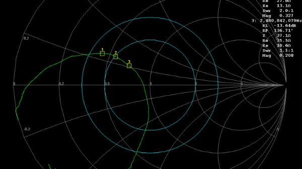
An article from Baseapp then makes for very interesting reading. Titled “Antenna tuning for beginners“, it approaches the subject from the perspective of miniature GHz antennas for IoT devices and the like. We’re taken through the basics and have a look at different types of antennas and connectors, before being introduced to a Vector Network Analyser, or VNA. Here is where some of the Black Art of high frequency RF design is laid bare, with everything explained through a series of use cases.

Though many of you will at some time or other work with these frequencies it’s very likely that few of you will do this kind of design exercise. It’s hard work, and there are so many ready-made RF modules upon which an engineer has already done the difficult part for you. But it does no harm to know something about it, so it’s very much worth taking a look at this piece.

It’s an area we’ve ventured into before, at a Superconference a few years ago [Michael Ossmann] gave us a fundamental introduction to RF design.

Hacklet 80 – Gigahertz Projects

Somewhere between the HF projects many of us have worked on, and the visible light spectrum lies the UHF, EHF, SHF, and THF. That’s Ultra, Extremely, Super, and Tremendously High Frequency for those who aren’t in the know. All of them involve frequencies in the gigahertz and terahertz range. While modern computers have made gigahertz a household term, actually working with signals in the gigahertz frequency range is still a daunting prospect. There have always been an elite group of hackers, makers, and engineers who tinker with projects using GHz frequencies. This week’s Hacklet is about some of the best GHz projects on Hackaday.io!

radar1We start with [Luke Weston] and Simple, low-cost FMCW radar. For years people like Hackaday’s own [Gregory L. Charvat] have been building simplified radar systems and documenting them for the rest of us. [Luke’s] goal is to make radar systems like this even more accessible for the average hacker. He’s put all the specialized parts on one board. Rather than large Mini Circuits modules, [Luke] went with Hittite microwave parts in chip scale packages. Modulation comes from a Microchip MCP4921 mixed signal DAC. The system works, and has demonstrated transmission and reception 5 GHz to 6 GHz bands. [Luke] has even demonstrated detection of objects at close range using a scope.

Continue reading “Hacklet 80 – Gigahertz Projects”

Horn Antenna

Building A Horn Antenna For Radar

So you’ve built yourself an awesome radar system but it’s not performing as well as you had hoped. You assume this may have something to do with the tin cans you are using for antennas. The obvious next step is to design and build a horn antenna spec’d to work for your radar system. [Henrik] did exactly this as a way to improve upon his frequency modulated continuous wave radar system.

To start out, [Henrik] designed the antenna using CST software, an electromagnetic simulation program intended for this type of work. His final design consists of a horn shape with a 100mm x 85mm aperture and a length of 90mm. The software simulation showed an expected gain of 14.4dB and a beam width of 35 degrees. His old cantennas only had about 6dB with a width of around 100 degrees.

The two-dimensional components of the antenna were all cut from sheet metal. These pieces were then welded together. [Henrik] admits that his precision may be off by as much as 2mm in some cases, which will affect the performance of the antenna. A sheet of metal was also placed between the two horns in order to reduce coupling between the antennas.

[Henrik] tested his new antenna in a local football field. He found that his real life antenna did not perform quite as well as the simulation. He was able to achieve about 10dB gain with a field width of 44 degrees. It’s still a vast improvement over the cantenna design.

If you haven’t given Radar a whirl yet, check out [Greg Charvat’s] words of encouragement and then dive right in!