The electrical grid transmits power over wires to our houses, and our Bryan Cockfield has covered it very well in his Electrical Grid Demystified series, but what part does the earth ground play? It’s commonly known to be used for safety, but did you know that in some cases it’s also used for power transmission?
Typical House Grounding System
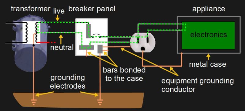
A pretty typical diagram for the grounding system for a house is shown here, along with a few of the current carrying conductors commonly called live and neutral. On the far left is the transformer outside the house and on the far right is an appliance that’s plugged in. In between them is a breaker panel and a wall socket of the style found in North America. The green dashed line shows the normal path for current to flow.
Notice the grounding electrodes for making an electrical connection with the earth ground. To use the US National Electrical Code (NEC) as an example, article 250.52 lists eight types of grounding electrodes. One very good type is an electrode encased in concrete since concrete continues to draw moisture from the ground and makes good physical contact due to its weight. Another is a grounding rod or pipe at least eight feet long and inserted deep enough into the ground. By deep enough, we mean to include factors such as the fact that the frost line doesn’t count as a good ground since it has a high resistance. You have to be careful of using metal water pipes that seemingly go into the ground, as sections of these are often replaced with non-metallic pipes during regular maintenance.
Notice also in the diagram that there are places where the various metal cases are connected to the grounding system. This is called bonding.
Now, how does all this system grounding help us? Let’s start with handling a fault.