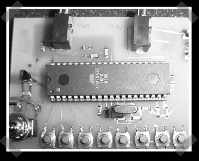
[Jason] sent in a couple tips, and this diy oscilloscope caught my eye. This design uses the A/D sampler on the ATmega to generate the signal for presentation on a regular CRT television. The sample limit is less than 16khz. Not terribly impressive, but not too shabby either.


15 thoughts on “Atmega Oscope”
Leave a Reply to tillzenithCancel reply
Please be kind and respectful to help make the comments section excellent. (Comment Policy)


16khz? You’re better off using your sound card.
to #1, its a scope, not a wave generator
@SuperJdynamite:
Not entirely true. What if you require several working places (e.g. a student’s lab) to have a scope each and have no money? The costs for this baby are close to nil and an old tv-set can be found in everybodys attic for free.
If you look at http://www.nbb.cornell.edu/neurobio/land/PROJECTS/ you’ll see lot’s of interesting stuff abt. neurobiology and there you don’t have to deal with frequencies above 2 kHz AFAIK.
The random track angles on the PCB makes me cringe!
Lol superjd. Quite true but its a nice little design nonetheless.
Yes there are plenty of programs to use your sound card as a scope. I doubt you would be very willing to use it for anything other than low level signal though.
http://www.zelscope.com/
Unless your computer is not worth anything to you?
Jason Rollette
Well a computer sound card can take a 1v p-p signal, this can take a 5v p-p signal, so a simple resistive divider would bring a sound card up to the same range as this… I would use a 100k/20k divider, with a pair of little signal diodes in antiparalel across the input to cap the voltage at about a volt (all of this on the computer side of the dc blocking cap) Add a program like zelscope and viola, digital scope.
The only problem I have with using a sound card is that it is ac-coupled at a pretty high frequiency, so it is hard to watch slow moving waveforms. This in combination with the slow sample rate really limits the overall usefulness of the scope to to audio range, and slow serial comunications. But this scope doesn’t solve that either.
So really the only advantage to this scope over a computer would be that it is smaller/more portable.
I think that the project would be more useful as a way to display info on a tv, that is a pretty impressive hack IMHO
The video output aspect of it is used by a lot of cornell EE students in their microcontroller course. I think the course notes discuss creating and synching a video signal. I ran across this site when googling for homebuild usb ir signal detectors (remote control readers)
http://instruct1.cit.cornell.edu/courses/ee476/FinalProjects/
here’s a very easy to build buffer to hook up oscope probes to your sound card. it was designed with xoscope for linux in mind, but it will work with any soundcard scope software, afaik. http://xoscope.sourceforge.net/hardware/hardware.html
I guess that answers my question. I asked a month or so ago if you could use a standard CRT (though I was thinking of interfacing with the deflection plates directly) as a basic oscilloscope.
#9 beat me to the xoscope buffer circuit suggestion, but as I just built the circuit and was playing with it (and xoscope) over the weekend I felt as though I had a couple of things to add. I used a simple 555 timer based circuit to out a square wave at various frequencies. I found that in order to see a wave form that actually resembled a square wave I was limited to the 3.5kHz -4kHz range. If you are just interested in the spectrum (like doing a FFT or something) you could go up to about 20kHz or so. (Note the sample rate was set at 44.1kHz). Just a little added info that I thought ya’ll might be interested in.
Regarding the buffer circuit for xoscope..
http://xoscope.sourceforge.net/hardware/hardware.html
.I dont understand what voltage is being used to power the opamp? Looking at the schematics the +12v and -12v is going thru diodes and then into the non inverting input and nowhere in the schematic does it show the voltage to power the opamp which would be pins 8 and 4. If anyone has sucessfully built this circuit please email me at zane7001@yahoo.com.
see tl082 site http://www.national.com/images/pf/TL082/00835703.pdf
thanks
Neal
Do anyone here know how to connect ATmega32 with computer?? How is that Atmega32 can be interfaced with Computer??
do anyone know how to interface ATmega32 with the Computer? How to communicate atmega32 and a computer??
@ #11/neal/zane
The reason that the power connections to the op-amp are not shown is that they are assumed to be connected. Since there’s little reason for building a circuit and not powering the chips, power connections are frequently taken as implied rather than drawn in.
The future is here! And dear past, I’m sorry to say that your links are broken, even though you’re still on the first page of search results for DIY AVR scopes.
So the important link is to the Cornell video generation page, as that is the interesting bit of the project. Here is a current link! If you’re coming here from the future, now you’ll have two archive entries to check for. ;)
http://people.ece.cornell.edu/land/courses/ece4760/video/index.html