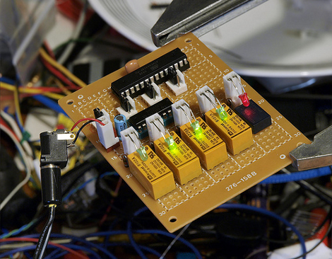
This device is lovingly called the SPINmaster. [Linux-works] built it to spin up multiple hard drives before the motherboard starts up. It detects the power-up from the PSU and uses a relay to hold the motherboard in reset, indicated by the red LED. Each of four relays then spins up a hard drive and illuminates the green LED when ready. Once all green lights come on the reset relay shuts off and the bios starts up. This type of staggered startup takes a lot of the load off of an under-powered PSU. He’s posted firmware and there’s a schematic available too. We took a look at his video but there’s not much to see as it’s just the inside of the machine while it boots up.


Mosfets can get hot when you put a lot of amps through them, namely audio amps and electronic speed controllers for RC cars & robots so they often use heatsinks for those, but I don’t think a harddrive would cause much heat in a decent mosfet as harddrives nowadays use an average of 0.5A @ 12v, less when idling.
@ReKlipz, lack of sound when the mosfet switches on/off can be compensated for by connecting a piezo speaker to the microcontroller. Just think of it, ringtones for your harddrive spin ups! ;) I’d go with classic arcade game ‘bleeps’
@linux-works: A relay supplied with its rated voltage, in a reasonable environment, should theoretically last forever. What kills it is switching, contacts can eventually wear away or weld together. But we are talking 500k cycles for yours!
A FET shouldn’t affect the circuit if the on resistance is reasonably low, and it is rated to take the continuous and surge current of the HDD (I have no clue what it is).
Skip the SSRs as they are usually isolated and rated for high voltages. Check out the “MOSFET, Bridge Drivers” section on digikey, I would recommend high-side switching with internal switch.
I think the startup pulse that hes talking about comes from the fact that the pins come up in the wrong state an have to be disabled as soon as the uc starts running.
you could use another io and a quad and/nand between the uc pins and the relay driver to have a master off function. this would take only 1 extra pin and some cheap parts.
I too would like to know the answer to NN’s question. How scalable are these?
no problem for more channels. no problem at all. the limit is the # of relay ‘ports’ and you can use a port expander chip (I like the i2c ones) and those give the same effect as ‘local’ digital pins. the speed is fast enough that the serial connect between the ard and the PE chip is ‘nothing’ to care about.
once you get past the extra port count, you just add relay driver chips (in ULN2003 for 7 relay ‘ports’ or the other ULN chip if you need 8). then just add PE chips and ULN chips together to get another block of 8. just that simple.
well, almost ;) you have to address them by their own i2c address. usually you have 8 (3 bits) addresses you can user-set. BUT, if you run out of those, you can go to another chip family and that’s a sneaky way to get more ‘address space’ to place more PE chips in.
the code would then map a block of 8 ports via the tuple {PE, offset} and you can walk each of the 8 ports in the port-group then move onto the next.
at some point, you run into space issues with ‘so many’ relays, though ;) those things eat into your space (and power) budget. also, if you start to get that many relays, it might make sense to look into latching ones; but those require extra hassle to talk to them.
@fdsa: I think the startup pulse that hes talking about comes from the fact that the pins come up in the wrong state an have to be disabled as soon as the uc starts running.
yes, exactly what I was referring to.