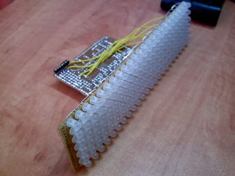
This LED matrix is arranged in a 24×6 pattern for message scrolling. There’s no etched boards here, making us wonder where [Syst3mX] found protoboard this long. He’s using an Arduino to drive the demonstration (clip after the break) but you can use any microcontroller with this setup. That’s because he’s using three shift registers for column data and a decade counter for row scanning, requiring just five control pins.
While you’re going to the trouble of ordering components, maybe you should try your hand at building a touch sensitive LED matrix too.
[youtube=http://www.youtube.com/watch?v=wNNTbhYPA94]


Sweet I want one!
Oh, you can buy 12×12 sheets of perfboard pretty easily. Usually you can find it where the plain copper clad boards are sold.
Pretty sweet, the LED’s look damn bright in the video.
and the source file is….chan chan chan chan…where????
This is relevant to my interests. I write software (Flex, AS, AIR) and just got my first Arduino board. I am wanting to learn how to make a simple countdown timer using the arduino to power a 7 segment led matrix. Does anyone know of a good starting point?
Some students at my uni made a LED scroller or discrete LEDs. Standard 5 mm LEDs, and the board has about one meter long in real life, with character height about 10 centimeters. I never saw the actual construction because the LEDs are behind a smoked persplex glass but that must hundreds of LEDs!
@ Entropia – Thousands… About 4 thousand I’d say from your description : op
Re: Long Perfboard, check Farnell, Roth Elektronik make some pretty (relatively) massive peices:
100mm * 580mm(!)
http://uk.farnell.com/roth-elektronik/re210-s3/pcb-prototype-re210-s3/dp/1221151
@rockrat
http://www.hacktronics.com/Tutorials/arduino-and-7-segment-led.html
That’s for a common anode 7-seg, if you have a common cathode, it’ll be different.
You might want to get some shift registers if you don’t want it to take up half your pins.
http://www.arduino.cc/en/Tutorial/ShiftOut
I’m thinking with a little tinkering this could be changed into a cheap system to control a huge block-controlled model train track with little hardware and little wiring.
Think “10 speeds” instead of “10 LEDs per column” and think “24 blocks of track” instead of “24 columns”.
Hmmm…
On a related note, I stumbled across an interesting technique for dimming LEDs called Bit Angle Modulation.
This technique works very well for controlling large LED Matrices because you only have update the LEDs once per bit of brightness resolution. IE, for 16 shades of brightness, you only have to update the LEDs 4 X refresh rate times.
http://www.batsocks.co.uk/readme/art_bcm_3.htm
@John- Would this be the file you seek?
http://www.instructables.com/files/orig/FYN/KCVK/GBVJ7WP0/FYNKCVKGBVJ7WP0.txt
allow me to save you the trouble of finding out (the hard way) what happens if you actually click the link.
Get more out of Instructables, by Signing up for a Pro membership!
PDF Downloads
Download and customize PDF’s of any Instructable. Learn more »
Digital Patches
Did someone make something really cool? Learn more »
All Steps Viewing
View all steps of an Instructable on the same page. Learn more »
Rich Text Editor
Get a full featured WYSIWYG rich text editor. Learn more »
Less Advertising
More good stuff.
Private Projects
Make your Instructables Private and get a special link for sharing.
Favorites List Pro Forums
Skip »
You don’t need to be a pro member, you can just sign up for free and get the source code
yea fill out a username and password bam you can see full articles
if that is too much for you then do you really need to be attempting to make anything?
@rockrat
While you can drive LED directly from the arduino like in this article it really isn’t the most practical/easy way to do it.
There are LED driver IC that require only a few pins on the arduino and will control hundreds of LED just by sending the chip the correct commands.
For standard digital display
http://www.maxim-ic.com/datasheet/index.mvp/id/1339
This one does text and has 104 ASCII letters ready to use.
http://www.maxim-ic.com/datasheet/index.mvp/id/3379
@cgmark
I had purchased the MAX7221 or its variant a while back to implement this, but I got stuck trying to figure out how to hook it up to the arduino. I know I need to use the arduino’s serial outs, but I didn’t know which pins went to which on the chip. I think I have the software figured out, but is it possible to consistently give commands via the usb (like ever 500 milliseconds) to update the display or is this writing to many times to the arduino?
Can someone explain to me why using a 4017 counter chip is a better solution than just using 6 output pins on the Arduino? If you still have to manually send a pulse to the 4017 to scan the rows there doesn’t seem to be any advantage except for freeing up 4 output pins on the micro. I suppose it would make the software a tiny bit easier/faster to send 1 pulse to the 4017 rather than controlling the state of 6 output pins, but is that the only reason?
@Brennan: Yeah, it’s used to free up pins. (perhaps for sensors or more shift registers etc)
Vector makes the best pad per hole boards, some quite long too