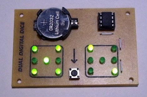
[Mike Shegedin] makes full use of an 8-pin microcontroller with this ATtiny13-based dice project. With a maximum of six I/O pins (that includes using the reset pin as I/O) he needed a couple of tricks in order to drive 14 LEDs and use a momentary push button for user input. We’re certainly familiar with the concepts here, but it still took quite a while to figure out what is going on with the schematic that [Mike] posted.
You’ve probably already guessed that he’s using Charlieplexing to drive more LEDs than he has pins. But when we started looking at the layout we thought he had drawn the schematic wrong, because there are six pairs of LEDs where the two diodes in each pair a not reverse biased, but hooked up in parallel. That, plus the fact that his battery is hooked up backwards. After several minutes of study the light bulb finally clicked on. Dice add pips (the dots on each side of a die) in pairs with the exception of the center pip. That means that you only need to control four total lines for each die (three pairs plus the center pip). There’s two ways to handle this, you could use four rows and two columns with traditional multiplexing, or you can reverse bias the two sets of LEDs for each die and use Charlieplexing. The former is a bit easier to program, the latter saves you one I/O pin and meant that [Mike] didn’t need to use the reset pin as I/O.
This is a clever addition to the collection of dice projects we’ve seen like the battery-less die, and the ATtiny2313 powered dice.


