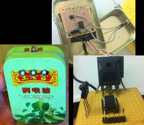
[Dmitry Grinberg] has to walk all the way across his bedroom to switch the lamp on and off. The drudgery of this finally became too much, so he built a remote control and added dimming for good measure. Above you can see the circuitry for the remote and the receiver, as well as the finished remote housed in what he calls a ‘Chinese Altoids tin’.
After the break you’ll find [Dmitry’s] demo video. The remote control is quite responsive, and the dimming has great resolution. That’s thanks to a power N-channel MOSFET which switches the AC with the help of a full wave rectifier. The PIC 12F617 that controls the MOSFET is powered separately, and [Dmitry] mentions that you must use a transformer and not a switch-mode power supply to avoid a fire. We’d like to know more about this, so leave a comment if you are able to explain further.
The remote and receiver communicate via Infrared. The protocol is operating with 38 kHz signals using an easily sourced receiver tuned to that frequency. [Dmitry] shares all the details about the encoding scheme that he uses. Recreating this communications pairing is a great way to test your understanding of this technique. But if you need a refresher, here’s a tutorial to push you in the right direction.[youtube=http://www.youtube.com/watch?v=tSn-VRLPo5I&w=470]


a properly designed isolated switching power supply will work. the transformer is used to isolate the tin case from the power line so that any inadvertent grounds cannot be accidentally shorted.
Yeah. There really is no reason to say anything like that.
A simple zener supply would work too. Might even be cheaper than the big FET he used.
Also, there should be a small inductor in series with the lamp to reduce flickering.
LOVE the mosfet with the rectifier!
@fai: yes a *properly designed* supply would. Since those aren’t in any way labeled externally as “properly designed” or “not properly designed,” I opted for the always-safe transformer choice. Isolation guaranteed.
Smart not using just any supply. There are more bad switching supplies on the market than good ones. I found one that relies on a capacitor/resistor for isolation from main.
@dmitry – simple test, you can do a simple test of a continuity test with any of the prongs on the live side. most switching wall warts for consumer electronics sold in north america and eu are tested for this. only imitation knockoffs might violate required certifications…
The rules are any supply that has a connection to the mains can do so provided the end user device has no way for a user to come in contact with the output power. So you can use a non isolated supply all you want in the USA as long as the device it powers is fully enclosed in plastic with no metal exposed that conducts the supply currents. Re-purpose one of those adapters though assuming it is isolated because it is in the USA and you can get a surprise.
Checking with a meter when the supply is unplugged also doesn’t always work because parts like diodes can lead to readings that appear to have no continuity but they actually do. The only real check is with the supply operating. Meter set to AC there should not be any voltage reading between the mains and the output wires.
to clarify – prong to +/- lead and all combinations thereof
éste es el mio y no ando presumiendo :)
http://www.youtube.com/watch?v=xoEDg57cDLo
i have the same IKEA lamp :)
great project, will build one too. dimming the lights from bed is pro style xD
I have built this one: http://hackaday.com/2009/02/07/ir-controlled-light-dimmer/
few years ago, and works GREAT :-)
@Jan: hope the schematics & code work for you. If not, email me :)
@Dmitry: i will port it to avr, i have no pic stuff lying around, shouldn’t be too hard i guess..
whats the price for all parts together?
So I understand that rectifying to DC will work fine with incandescents, but would this work with CF bulbs as well?
The only part I pad for was the MOSFET. The PICs I had lying around, and the rest I got from some old boards which I usually solder components out of
could easily power the mcu directly from the rectified DC with a large value resistor in series with a diode, connected to the V+ pin. Then, from the V+ to V-, connect a capacitor and a zener diode to set the voltage to the range acceptable for the MCU (usually 3.3v or 5v). Choose resistor value based on current draw of the MCU, and maximum shunt current of the zener. Then you eliminate the external power supply