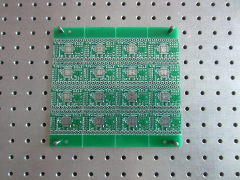
[Zach Hoeken] has the answer to assembling multiple surface mount PCBs in the home workshop. It’s certainly not for everyone. But if you’ve ever thought of marketing your own small runs he has the equipment and methodology you need.
He had tried using hacked together equipment, but after encountering a range of issues he finds the investment in a few key items saves time and money in the long run. The first is a precision tooling fixture block; that metal plate with a grid of holes that makes up the background of the image above. It comes with machined pegs which fit the holes perfectly, and as you can see, his panel of 16 boards include tooling holes that line up with the fixture. Once in place, a steel solder stencil is aligned with the board using its own tooling holes. The alignment of the stencil and its uniformed thickness ensure that the perfect amount of solder paste is easy to apply with a squeegee. [Zach] hand places his components but he did invest in a proper reflow oven to make the soldering a set and forget process.


We actually have that reflow oven, we bought it off Ebay new for $168. It was quicker and cheaper than hacking our own when you take into account the time that would be spent hacking a toaster oven. Been using it almost daily for 9 months with no problems.
The big issue is step 6 in his list…placing the parts…man now that 3D printing is everywhere can we please open source a simple pick and place for a grand?
I agree completely. I’ll be trying to build a DIY pick and place machine… hopefully you’ll see my results on Hackaday later this year or next!
http://blog.screamingcircuits.com/2007/04/soldermask_via_.html
If I was going to do it I’d just 3D print stencils for a pick and place.. More efficient and accurate.
I’d also buy a cheap flow over though.
Yes, sure… The day when you can 3D-print a 0.1mm thick sheet with holes that are down to like 0.2mm wide in it I’ll buy one of those machines. :-)
Until then laser cut mylar/kapton or real stainless steel stencils are my choice..
Is there a reason you can’t use thin acryllic instead of steel for the solder stencil? I’m just curious what the limitation is, as lasers that can cut acryllic are much more widespread than ones that can cut steel.
Kapton – http://ohararp.com/Stencils.html
and
Mylar – http://www.pololu.com/catalog/product/446
is already being used as cheap low-volume stencils and they are cut with regular 40/60 watt lasers.
The mylar distorts and warps by the heat from the laser – not a good thing for small precise holes. The kapton is more stable but more expensive as well.
The main difference between the cheap plastic versions and stainless steel stencils is the durability. A steel stencil can be used *many* times, the plastics not so much.
I can see two improvements for your system right off the top.
1) Add ridges to your hold down pins so that your board is held off the base the height necessary for your through hole parts. This will allow you to solder everything at the same time.
2) Since you have a metal laser cutter, create an additional template that allows you to drop your SMDs in place. This will allow for quicker placement of parts while at the same time assure even alignment and neatness. By having the plate half the thickness of the parts or set up off the board slightly, you should be able to remove the board without disturbing the parts. It may be possible to 3D print such a board.
Take care.
We love to see this kind of DIY stuff!!
Bubba Gump…your own reflow oven?? I’d love to see a picture of your workshop!
For anyone looking for a source for the pictured Stencil8 tooling fixture block, I’ve started selling them here: http://forre.st/stencil8