It couldn’t be simpler but you have to admit that a small adjustable portable power supply like this one will be really handy.
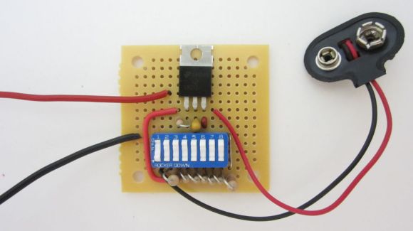
The main part of the PSU is an LM317 linear voltage regulator which we’re already familiar with. The output voltage is adjustable based on a voltage divider between two of the pins. The set of eight DIP switches allows you to tweak that voltage divider. Switch number one connects the 9-volt battery connector to the regulator, serving as a power switch. Each of the other seven switches adjusts the output voltage by 1.5 volts. The output of the regulator connects to your target device using alligator clips which are not in frame above.
[Jason] says he takes this with him when thrift store hunting for cheap electronics. It can mimic most combinations of Alkaline cells letting you power up electronic toys to ensure they work. But we would find it equally useful for getting that early prototype away from the bench supply for testing before finalizing a dedicated portable supply.


Simple… elegant.
yep
now to modify it so that led’s light up at each voltage point and mount it in a altoids tin with banana jacks for ever easier use
I like this a lot… But where’s the Arduino?
jk :)
Couldn’t this be easily implemented using a Raspberry Pi?
Nah… Why don’t you just buy a couple of power sources with varied voltages? Radio Shack already sells things like that…
Now serious: I liked the idea. I think you could hook up this setup to a 12V, 2A power source, a heat sync and get a very good adjustable power supply.
And mounted in a 3D printed case!
FPGA…
or use less dip and resistors like (270ohm x dip position) to get binary code for voltage.. :)
I was thinking this was the approach when I saw the title.
“Turing on switch 1 turns on the circuit and brings the output up to 1.25V” and not “Each of the other seven switches adjusts the output voltage by 1.5 volts.”
It’s both. Switch 1 is the power switch. With all of the dip switches closed, the adjust pin is tied to ground, so it’s at 1.25v. Each switch opened at that point will increase the voltage by 1.5v. (1m36s in the video)
Those are some very crude steps.. so you get 1.25, 2.75, 4.25, 5.75, 7.25, 8.75? that makes it nearly useless for most things. Why not 1.5v 1.8v 2.5v 3.3v 4v 5v?
Nearly useless for what things? I have a couple of 3.3v wall-warts, but I have no idea what they came from and I’ve never actually owned anything which runs on 3.3v external power.
can i tell you a secret……..most common rechargeable batteries(AAA,AA,C,D) are actually 1.25v, and not the ‘standard’ 1.5v……yet they have no problem running standard electronics.
99% of consumer electronics actually fairly electrically ‘imprecise’…….because honestly, they dont need to be.
if something will run at 3v….there is a good chance its also going to run fine anywhere from 2.75-3.25V
Yo do realize yo can use any resistors you want to get any increment you want?
You can also solder the resistors laying flat and use a slide switch to make it even thinner. And while using a slide switch, the resistor array must have incrementing resistance as well to accommodate the slider switch. I’m making one later on.
Great idea but DIP switch seems too fiddly – next version with a rotary switch ?
DIP switches are way cooler than grandpa’s old rotary switch
I’ve done something similar using a potentiometer instead of the dip switches/resistors. However, this is elegant, simple, effective, and you don’t need a meter to tell you what the output voltage is.
I like it.
Great idea and well done!
He used the first position dip switch as power on switch. I wonder how much current this type of dip switch can handle as they are primarily made for logic input.
I also thought about this. Similar DIPs i foudn Datasheets for are rated:
CONTACT RATING:
Carry: 100 mA max.
Switch: 100 mA max. @ 5 V DC or 25 mA max. @ 24 V DC.
http://www.datasheetarchive.com/8%20Position%2016%20Pin%20SPST%20dip%20switch-datasheet.html
That’s surprisingly little, for a switch.
Nice idea but I think I’d prefer one of the super cheap LM2596 based boards available on eBay – such as:
http://www.ebay.co.uk/itm/New-1-23V-30V-1pcs-DC-DC-Buck-Converter-Step-Down-Module-LM2596-Power-Supply-Out-/400522245660?pt=UK_Home_Garden_PowerTools_SM&hash=item5d40fc761c
MOD:
I blindly put my full name in the comment box – could you please change it as per below? Thanks :)
Philip Strong, is that you?
How did you guess :O
If you didn’t asked to change your name on the comment, nobody would notice. As you stated this, now everybody knows you don’t want to be known, and we just told NSA to watch you.
And have a nice day!
en.wikipedia.org/wiki/Streisand_effect
Yeah on second thoughts I could probably have just lived with the world knowing that I know about something on eBay. I guess this is a good indicator of how good the moderation is on here!
a ha! we’ve found you at last Philip Strong! PRISM is pointing you now! XD
Signed.
The Happy NSA Surveillance Team
P.S. This DIP switch hack is very cool!
I have always implemented small variable voltage supplies like this by simply using a multiturn variable resistor….. Remember kids: You must put a load on the LM317 series in order to read the “operating voltage” …. If you leave the outputs floating, then the output voltage can vary wildly. This caused me all kinds of headache trying to figure out why my 317 supplies produced wildly different voltages from what I expected to see…..
Bringing this to thrift shops is an excellent idea.
“Tonight on your local news: are terrorists arming your thrift store?”
Very nice. Great Job!
Great! I made it even smaller and breadboard-able!
Check this out:
http://indiantinker.wordpress.com/2013/02/16/micro-bread-board-adjustable-power-supply/
Thats effing nifty man. You should have submitted it to HaD for publication..
Thanks !! Will Do.. :D
I’m going to deliver this in the complement sandwich approach:
Great project!
Having a tiny screw pot requires an extra tool to operate and kills the design.
I like your style.
Thanks for the comment Caleb!
I did realize the fact and made a version with a thumb-pot too;which was apparently easier to operate but, i usually use it to experiment with OPAMP`s where i require very precise control of voltage level.
Will surely post the pics of the thumb-pot version too. :D
Headers and DIP jumbers would be less likely to accidentally change if you brush against the DIP switch.
I like the DIP jumpers idea, should allow alot more current than the DIP switches if the above linked specs are close to what was used.
I made a variant of this for laser diode testing, works well BUT needs output restriction via Zener diodes to stop the laser eating itself.
Could you wire in another 9v battery to get an adjustable voltage up to 18v?
How would you wire in a switch to have two banks of batteries? (I.e. When the first 9v is depleted you could flip switch to second 9v). I’m asking because this could come in handy in so many ways.
You can put a second 9v in series and the switches will give you 10.25, 11.75, 13.25, etc. The LM317 will actually go up to 30v this way. You can do higher voltages as well as long as the *difference* between input and output is not over 30v.
A simple DPDT switch can swap two banks of batteries.
Meant to comment on this yesterday but forgot to hit submit, the most important part lol. Love this! It is a simple circuit, can be used for a variety of applications, and is a good one for teaching soldering, troubleshooting, and board layout skills. Nice :) Already built a couple (Thanks to Jameco sending me 8000 dip switches in a grab bag order lol). I added a simple multi-barrel tip from an old wall wart multiadapter and can accommodate a variety of sizes and polarity swap on the fly :) Fun project!
i’m looking to control a power supply with pwm, what is the best way to do so?
Can you be more specific?
Do you want to control the voltage output from a simple linear voltage drop regulator like the LM317 using the PWM from an arduino?
Do you want to build a boost/buck power supply from scratch using only discreet chips?
i thought about pwm the LM317, like here:
http://ruggedcircuits.com/images/sch14.png
but wonder: a)does it work b)is this the most efficient way to do so?
If your looking for efficiency go with a buck power supply. Or better yet a boost power supply and less batteries. Check out the minty boost for a simple example.
That circuit doesn’t directly control the LM317 using a PWM signal. It uses the 47K resistor and 0.1uF C1 to convert the PWM into a voltage, like a simple DAC. The Opamp buffers and scales that voltage to set the reference voltage of the LM317.
I have to admit. I suck at electronics.
Now can someone tell me if a voltage regulator above save energy or not? If a 9V battery has 500mAh rating. And it is using the voltage regulator to output at 3V, what would the power rating be?
A simple formula to find efficiency of a LM317 is Efficiency = 100%-(Vin-Vout)/Vin. This ignores the power being used by the LM317.
So your example of a 9V in and 3V out gives 33.3% effiency because 1-(9-3)/9=.333
Your 9V battery with a 500mAh capacity would give 3V with 500mAh using this circuit with no losses in an ideal world ignoring all current going through the resistors and at a perfect discharge of your 9V.
The difference in voltage is wasted. If you put 9 Volt in, and get 3 Volt out, the LM317 drops 6 Volt. If the current is 1 Ampere, that means that 6 Watt is turned into heat (power = voltage * current).
This means that the total power use is always the same, it is the voltage going in * the current. If you turn down the output voltage, it just means that a bigger part of it ends up in the heat sink.
To get the power rating at 3V, you need to look up the data sheet. There you will read “Output-Current In Excess of 1.5 A”. Let’s take the 1.5A. Then the power supply can deliver 3V*1.5A = 4.5W. However, at the input, there will be 9V*1.5A = 13.5W. The LM317 will be consuming 9W itself.
I found out the hard way thees type of regulators are not useable for battery applications unless you use a real power switch (ie no soft power) because the draw 7ma just sitting there doing nothing. A cmos low quiescent current (in the nano amp range) regulator is a better choice..