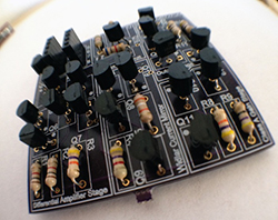
 By now we’ve all seen the ‘Three Fives’ kit from Evil Mad Scientist, a very large clone of the 555 timer built from individual transistors and resistors. You can do a lot more in the analog world with discrete parts, and [Shane]’s SevenFortyFun is no exception: it’s a kit with a board, transistors, and resistors making a very large clone of the classic 741 op-amp, with all the parts laid bard instead of encapsulated in a brick of plastic.
[Shane] was inspired by the analog greats – [Bob Pease], [Jim Williams], and of course [Bob Widlar], and short of mowing his lawn with goats, the easiest way to get a feel for analog design was to build some analog circuits out of individual components.
[Shane] has a few more kits in mind: a linear dropout and switching regulators are on the top of the list, as is something like the Three Fives kit, likely to be used to blink giant LEDs.


laid bard*
The bared parts are laid bare.
And yes, they aren’t the same chip off the ol’ block. That why they made tx arrays in chip form.
I like this trend but I think I’m going to hold out for the discrete 6502 kit. Even though ti will cost more than my car and be several square feet it will be totally rad to hook it up to my Atari 2600 and play classic video games on a discrete CPU.
You could totally fit that in a 4-6 unit rack.
Atari 2600 had a 6507 internally: just like the 6502, but without the interrupt lines and top three address bits. That could save you some time off your project!
Verily, the parts be laid bard. Forsooth!
Since most common IC’s are just packaging for passive(and active) analog parts(even many digital IC consist of arrays of analog components), projects like these are an excellent learning tool and teaching aid.
Not to mention, you could probably scale up the power handling capabilities that are found in the IC’s… I could see a 30 amp single “chip on a board” voltage regulator. Not necessarily progress, but definitely more thermal capacity with the wind blowing through all those discrete parts.
Hell, throw in some tubes while you’re at it >:)
I wish I could somehow hack together doped silicon to make a tiny integrated circuit instead of these discrete component designs. One of my favorite classes was designing op amps in SPICE. I don’t have a good idea for this yet though. :(
Operational Amplifiers were originally produced in vacuum tube modular units in the 50’s and early 60’s. One class I had we had to breadboard an op amp from discreet components. The hard part was getting a good match for the transistors. I believe Bob’s last name is spelled Widlar.
And it was not a goat, he would never do that. It was a sheep. Bob Pease must know:
http://electronicdesign.com/analog/what-s-all-widlar-stuff-anyhow
Excellent series of articles.
Besides that, I like this starting trend that people think about analog stuff again.
I like this trend of thinking about things too, it’ll never catch on!
People seem to view analogue as somehow obsolete or not relevant when in fact it’s pretty consistently at the leading edge of awesome. Digital tends to just come down to cramming more transistors onto something, beating problems to death with CPU cycles or storage. Analogue can come up with some truly beautiful solutions to problems.
I believe ‘discrete’ is spelled ‘discrete’.
Much of the theory of current mirrors and differential pairs is based on the premise that the whole chip is at the exact same temperature and transistors are identical (because they have been fabricated at the same time and only a few microns apart from each other). A discreet version will probably have very low performance.
Not a problem, if a curve tracer is available. Then take several transistors and find matching pairs with similar gain. The rest is done by trim pots.
Did this once with the front end of a Keithley 602. Someone applied excessive voltage and fried both 3N163 isolated gate FETs of the differential input amp. So I ordered 10 3N163s from ebay and matched them on a Tek 7CT1N. The mismatch is compensated each time prior ti use by the “center zero” pot and 2 switchable resistor arrays in the instrument.
Curve tracing, ah! It’s as if they’d solved all this stuff before IC’s had been invented…
A discrete version can be optimized for much higher S/N, 120dB isn’t unheard of.
I did a batch of discrete 741 boards about a year ago, but I’ve never soldered up any of them. Maybe it’s time to do that. :-)
Here’s a photo of it:
http://s27.postimg.org/s52t9435f/IMG_20140706_122345.jpg
Yeah, I wonder how difficult it is to actually get them to work :) I mean, some of the circuit tricks rely on the fact that you have thermally coupled and relatively well matched transistors on the IC. It may be more tricky with discrete components.
Hey Matseng! I have a bunch of your little USB breakouts from Tindie. Cool stuff.
I’m laughing because this discrete-741 idea seems to have occurred to so many people — it’s been on my todo list since the discrete 555 came out, and I wonder if there are any other actual implementations extant.
I feel like deconstructing common ICs like this is probably a great exercise in teaching yourself the analog side, being able to probe all the internal connections and make changes to see how it all responds.
Is anyone aware of an EE curriculum that involves such replica builds?
I know it would be a lot of work / impossible for my current EE level but i think about making a CPU with analog component no chips. also that it be designed by a computer based on a given input / output. essentially let a computer evolve a board to do what i want it to like ram IO peripheral ect. the have it auto generate Gcode for the CNC of the tracks and for a pick and place to add the SMD components.
on an unrelated note cryton computing in a space environment where there is low solar radiation would mean you don’t have to heat the craft to run computers/traditional electronics affectively as they require extreme low temperatures to function already.
Neat idea! Why are the components not soldered on the kickstarted board?
My guess is that they were either pressed for time or just plain enthused and/or wanted the cleanest looking representative picture possible.
mmmmm ….. im tinking of a simple guitar distortion pedal – just this circuit with some coupling caps, a pair of diodes clipping to ground – hell , no input buffer…. this would be very nice for that , as i could shape the sound inside the opamp, not just outside it…. :)
eeeek! Why bother? op amps are great because they are simple and easy to use. and very generic,
-e.g. I can make inverting, non inverting, unity buffer, voltage comparators etc all from one really cheap component. it’s so ubiquitous that most people have the pin out memorised!
But they are also hideously complicated for that use if you stop it being a “black box”
You’re making a handful of long tailed pairs, plus common collector/emitter follower and common emitter amps.
If you’re looking for an amplifier for use in a simple fuzz box then why not use a single simple common emitter based voltage amplifier, -that’s 1 transistor and 3 or 4 resistors.
(using 1 of these amps assumes you don’t care about the phase shift using 2 would correct that)
You can build a few stages to select various overdrives, and looking at the data sheets can determine where you want your amp to operate with regards biasing the cut-off/saturation region. -and there is no point in saying you don’t want to look at the data sheets to understand that because you’ll almost certainly _need_ to in order to understand how bias the whole load of amps in the 741 copy circuit.
For sure, moving away from the black box of trick that is the 741 (and other pin compatible chips, is good, but blindly copying the huge box of tricks when you only need one function will kick your ass unnecessarily.
This is cool for learning, you can measure what’s going on inside, but as an actual “thing” to be made into a circuit you’re probably better thinking about what you actually want to do with the signal, and using the appropriate blocks to get that done, -in short there is little sense in trying to replace a small 741 with an exploded 741, when your application quite probably doesn’t warrant all the functions of a 741. -a guitar pedal *almost certainly* doesn’t!
Haha ! thats exactly the point ! I have made various pedals with various opamps, power amps and hex invertors.
Self biasing single tranny circuits are not great sounding (to me anyway)
And im sick of TS9 / Tube Screamer clones, and Fuzz Faces and variants, i have made too many ! I could solder one of them up in my sleep! :)
Im in no way an electronics or soldering guru, but I can see oportunity in this for some cool mojo sounds…. Im not interested in what functions are not used, if anything the aethstetics of this circuit with just a few caps and resistors, maybe a couple of diodes, would be worth it , just to get rid of the little black box…..
Form over function – definatley !
So you’ll replicate a 741 in discrete silicon to get rid of the chip?
If that’s the end game then great…
But I don’t get the benefit, makes it look a bit better/makes it look more complex?
But I think the point does stand that a lot of times it’s easier to start design and work out what in the way of amplifiers filters etc you need to get there. Rather than start with a working system and try to butcher it into something else….
Though to be honest you could have done that at any time the 741 circuit is very well published and explained already… (This kickstarter doesn’t enable you if you already know what you’re doing!)
I like this. Seems like there’s a lot of potential for educational value. Imagine using a dis-integrated 555 in a breadboarded circuit instead of the IC… Suddenly it seems a lot less like some arcane magick, doesn’t it?
I wonder if the circuit’s laid out in a manner that would make it feasible to add an acrylic panel with a 1:1 laser-etched overlay of the schematic, or if it’d just be a mess…
My version http://s27.postimg.org/s52t9435f/IMG_20140706_122345.jpg actually have the schematics as the layout. And convenient test points marked out on the pcb.
Cool! I like the DIP package shaped PCB, nice touch. :D
“Ships within the US only”
Why do all the awesome kickstarters do that? :/