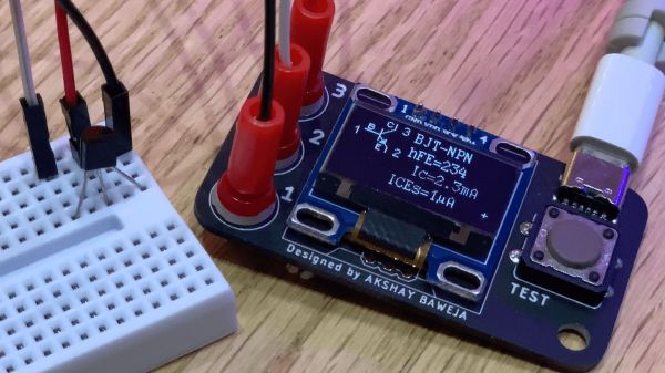
The ideal component tester is like a tricorder for electronics — it can measure whatever it is that you need it to, all the time. Maybe you have a few devices like an ohmmeter and maybe a transistor socket on our multimeter. But what do you do when you need to see if that thyristor is faulty? [Akshay Baweja] wants an everything-tester at the ready, so he’s building a comprehensive device that fits in a pocket. It will identify the type and size of: Continue reading “Check Your Pockets For Components”
component8 Articles
Components Cut In Half Reveal Their Inner Beauty
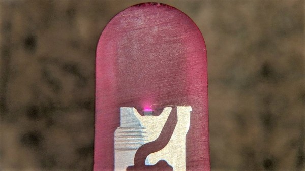
We rarely take a moment to consider the beauty of the components we use in electronic designs. Too often they are simply commodities, bought in bulk on reels or in bags, stashed in a drawer until they’re needed, and then unceremoniously soldered to a board. Granted, little scraps of black plastic with silver leads don’t exactly deserve paeans sung to their great beauty – at least not until you cut them in half to reveal the beauty within.
 We’ve seen a little of what [Tube Time] has accomplished here; recall this lapped-down surface-mount inductor that [electronupdate] did a while back. The current work is more extensive and probably somewhat easier to accomplish because [TubeTime] focused mainly on larger through-hole components such as resistors and capacitors. It’s not clear how the sections were created, but it is clear that extreme care was taken to lap down the components with enough precision that the inner structures are clearly visible, and indeed, carefully enough that some, most notably the LED, still actually work. For our money, though, the best looking cross-sections are the capacitors, especially the electrolytic, for which [Tube Time] thoughtfully provides both radial and axial sections. The little inductor is pretty cool too. Some of the component diagrams are annotated, too, which makes for fascinating reading.
Honestly, we could look at stuff like this all day.
Thanks to [Stuart Rogers] for the tip.
Searchable KiCad Component Database Makes Finding Parts A Breeze
KiCad, the open source EDA software, is popular with Hackaday readers and the hardware community as a whole. But it is not immune from the most common bane of EDA tools. Managing your library of symbols and footprints, and finding new ones for components you’re using in your latest design is rarely a pleasant experience. Swooping in to help alleviate your pain, [twitchyliquid64] has created KiCad Database (KCDB). a beautifully simple web-app for searching component footprints.
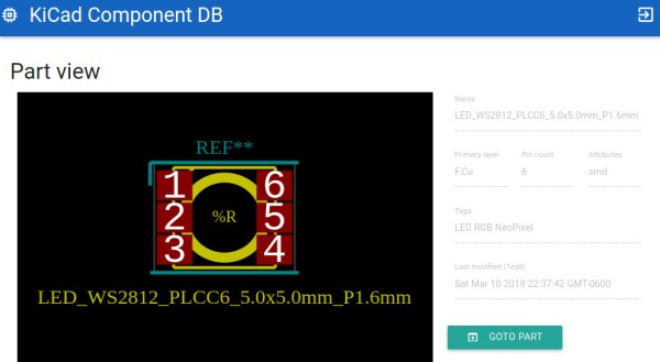
The database lets you easily search by footprint name with optional parameters like number of pins. Of course it can also search by tag for a bit of flexibility (searching Neopixel returned the footprint shown above). There’s also an indicator for Kicad-official parts which is a nice touch. One of our favourite features is the part viewer, which renders the footprint in your browser, making it easy to instantly see if the part is suitable. AngularJS and material design are at work here, and the main app is written in Go — very trendy.
The database is kindly publicly hosted by [twitchyliquid64] but can easily be run locally on your machine where you can add your own libraries. It takes only one command to add a GitHub repo as a component source, which then gets regularly “ingested”. It’s great how easy it is to add a neat library of footprints you found once, then forget about them, safe in the knowledge that they can easily be found in future in the same place as everything else.
If you can’t find the schematic symbols for the part you’re using, we recently covered a service which uses OCR and computer vision to automatically generate symbols from a datasheet; pretty cool stuff.
Custom Parts Feeder Aims To Keep Pace With Pick And Place
When your widgets have proven so successful that building them gets to be a grind, it might be time to consider a little mechanical help in the form of a pick and place machine (PnP). If you’re going to roll your own though, there’s a lot to think about, not the least of which is how to feed your beast with parts.
Managing the appetite of a PnP is the idea behind this custom modular parts feeder, but the interesting part of [Hans Jørgen Grimstad]’s work-in-progress project has more to do with the design process. The feeders are to support a custom PnP being built in parallel, and so the needs of one dictate the specs of the other. Chief among the specs are the usual big three: cheap, fast, and reliable. But size is an issue too insofar that the PnP could be working with dozens of component reels at once. Flexibility was another design criteria, so that reels of varied width can be accommodated.
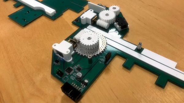
With all that in mind, [Hans] and company came up with a pretty slick design. The frame of the feeder is made out of the PCBs that house the motors for handling the tape, and the ATmega168 that controls everything. Tapes are driven by a laser-cut sprocket driven by 3D-printed worm gears. The boards have fingers that mate up to the aluminum extrusion that the PnP will be built from, and at only a few millimeters wider than the tape, lots of feeders can be nestled together. The video below shows the feeder undergoing some tests.
Alas, this build isn’t quite done, so you’ll have to check back for the final schematics and PCB files if you want to build one for yourself. While you’re waiting, you might want to build your own pick and place.
Continue reading “Custom Parts Feeder Aims To Keep Pace With Pick And Place”
Make Your Own Reed Switches
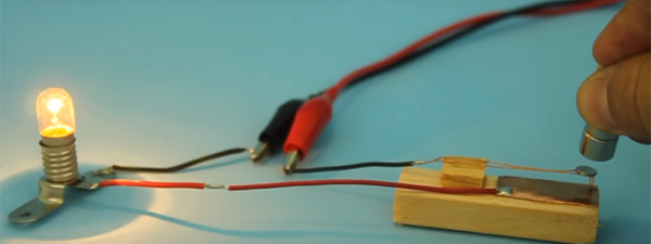
[Lucid Science] shows us how to make some simple reed switches. Reed switches are simple components that detect a magnetic field and can close or open a circuit once detected. While not really a thing of beauty, these DIY reed switches should help you out if you just can’t wait to order some or you fancied trying your hands at making some components from scratch.
Reed switches normally come in very small form factors so if you need something small then this may not be for you however the video does show you on a macro scale the fundamental workings of a reed switch. To make your own reed switch you need only a few parts: some copper, enamelled wire and magnets. They really are simple devices however sometimes it’s easy to overlook how simple some things are when they are so small that you can’t really see how they work.
Making your own components from scratch is probably the best way to understand the inner workings of said component. In the past we have seen some pretty awesome self built components from these beautiful DIY Nixie tubes to even making your own LEDs
The Disintegrated Op Amp
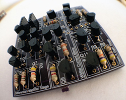 By now we’ve all seen the ‘Three Fives’ kit from Evil Mad Scientist, a very large clone of the 555 timer built from individual transistors and resistors. You can do a lot more in the analog world with discrete parts, and [Shane]’s SevenFortyFun is no exception: it’s a kit with a board, transistors, and resistors making a very large clone of the classic 741 op-amp, with all the parts laid bard instead of encapsulated in a brick of plastic.
[Shane] was inspired by the analog greats – [Bob Pease], [Jim Williams], and of course [Bob Widlar], and short of mowing his lawn with goats, the easiest way to get a feel for analog design was to build some analog circuits out of individual components.
[Shane] has a few more kits in mind: a linear dropout and switching regulators are on the top of the list, as is something like the Three Fives kit, likely to be used to blink giant LEDs.
Assigning New Packages To Eagle PCB Components
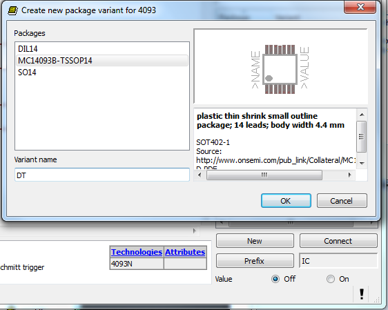
If you’ve spent any time at all laying out your own circuit boards we’re sure you’ve run into the issue of not having the right component or package available in the standard libraries. If it’s a common part, chances are the symbol definition will be there. But perhaps the footprint you want to use is missing? Here’s an easy to follow tutorial which demonstrates how to assign new packages to existing Eagle PCB components. It even shows the basics of how to tweak the footprint to fit your needs (like making SMD footprints easier to hand solder).
This will not teach you how to make your own custom symbols, or how to build packages from scratch. But it will let you locate the package you want to use from a different component, then copy it to your own library for use with different parts. And the techniques shown make this a quick and relatively painless process.
We certainly don’t want to start another comment quagmire like the recent PIC v. AVR discussion. But we’ve used both Kicad and Eagle rather extensively and feel that neither one has really mastered part/footprint creation in a user-friendly way. We like Kicad’s total separation of footprints from components, and it’s myriad of parameters which can be used to tweak the layout. But if you use the same components frequently, Eagle’s standard of linking parts and footprints does end up saving a lot of time. What do you think?

